Continue to Site

Welcome to our site!

Electro Tech is an online community (with over 170,000 members) who enjoy talking about and building electronic circuits, projects and gadgets. To participate you need to register. Registration is free. Click here to register now.

  • Welcome to our site! Electro Tech is an online community (with over 170,000 members) who enjoy talking about and building electronic circuits, projects and gadgets. To participate you need to register. Registration is free. Click here to register now.

Disco light wire coding

Status
Not open for further replies.

llyr_roberts

New Member
Hello!

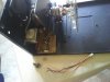
I have an acme disco light i was giving some TLC to.

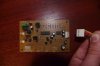
It has a nob for adjusting the sensitivity for sound to light, it's a 16mm 100K pot but the wires connected to it have been ripped off.

They are Red, black and brown. (PIC ATTACHED)
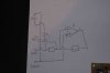
Which pins of the pot should each of theses wires be soldered back onto?

Would brown be zero/ground in this case? And the other too no matter?

Is there a way to use my multimeter to find out?

Thanks
Llyr
 

Attachments

  • 2011-04-07 16.20.10.jpg
    2011-04-07 16.20.10.jpg
    1.6 MB · Views: 327
If you don't have the knowledge to trace the circuit and figure it out I would add a 50k resistor to the pot's middle pin and try all combination until you find the one that works best. when found, remove the resistor.

Mike
 
Last edited:
Can you give an idea what the terminal strip terminals are attached to component wise? Like terminal 3 goes to + of a 100 uf cap and the - goes to pin 3 of an LA334 IC. Terminal 4 appears to go to ground.

Bottom line, you only have to get the middle terminal right. If you get the ends right, the sensitivity direction would be wrong.
 
I'll give it a go!

terminal 1) The black cable coming out of one of the pots terminals goes in into the board is joined to one side of the microphone and then into pin 3 of a KIA 358P so a +Ve opamp input!

2) Brown cable (from pot) goes into board - joined to other side of mic through cap - then through resistor connected to another resistor then going into pin 1 and 2 of opamp so Vout and -Ve/inverting input.

3) Finlay Red goes from pot into board goes to the first resistor mentioned above.

Right Ive taken a picture of both sides of the board and flipped the image so it matches up when put side by side hope this helps!! (attached)

Thanks!
 

Attachments

  • IMGP0551flip.jpg
    IMGP0551flip.jpg
    398.7 KB · Views: 301
  • IMGP05501.jpg
    IMGP05501.jpg
    398.4 KB · Views: 291
I've tried to work it out on paper (diagram pic) surly the brown and +Ve input of op-amp would go to ground, so pin 1 of the pot should be soldered to the brown wire.

How do i figure out which way the other two wires should go?

Thanks
 

Attachments

  • diagram.jpg
    diagram.jpg
    176.8 KB · Views: 280
Red = CW
Brown = wiper
Black = CCW

Install pot at mid range. Check sensitivity direction with labels for control. If incorrect, reverse CW and CCW.

Black is probably connected to power supply ground.
 
Status
Not open for further replies.

Latest threads

New Articles From Microcontroller Tips

Back
Top