Continue to Site

Welcome to our site!

Electro Tech is an online community (with over 170,000 members) who enjoy talking about and building electronic circuits, projects and gadgets. To participate you need to register. Registration is free. Click here to register now.

  • Welcome to our site! Electro Tech is an online community (with over 170,000 members) who enjoy talking about and building electronic circuits, projects and gadgets. To participate you need to register. Registration is free. Click here to register now.

directly heated valve biasing

Status
Not open for further replies.

the cracken

New Member
im trying to work out the resistance values for a single stage miniature valve preamp. im using a 6418 triode valve heres the data sheet... https://www.electro-tech-online.com/custompdfs/2010/04/6418.pdf

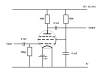
i want to make a distortion pedal with it so i though it would be best to have it self biasing to stop me from stripping the cathode when i over drive it. the problem is that it is a directly heated valve. im not sure how to power the filament. do i use a separate voltage source or does the cathode resistance drop a voltage to power it?? doesn't the filament resistance have an effect on the voltage drop on the grid? ill put a little diagram up that i made in paint!
and one last thing what the smeg do i do with the screen grid put it to +vcc? make it adjustable??

**broken link removed**

i didn't put in the coupling capacitor's and the output is on the anode (i know its a bad diagram)

any help would be appreciated!!
 
the anode and cathode resistors are there to allow a current of 0.5ma though (max cathode current) and to give a 1.5v drop on the grid
 
Last edited:
For a directly heated cathode you need an isolated heater supply, or use negative bias on the grid.

Far better to use a more sensible valve with an indirectly heated cathode.

Seems a bit pointless having two cathode resistors as well?.
 
For a directly heated cathode you need an isolated heater supply, or use negative bias on the grid.

Far better to use a more sensible valve with an indirectly heated cathode.

Seems a bit pointless having two cathode resistors as well?.


the one on the right is the cathode resistor the one on the left was meant to be for a separate supply but i didnt put it in because i wasnt sure!
ill put up another pic of what iv got so far! but im not sure what to do with grid2???
**broken link removed**
 
G2 normally connects to the positive supply, via a resistor, or is joined to the anode (triode mode).

Your heater supply needs to be floating, you can't connect it to chassis like that, it needs to connect directly across the heater,
 
G2 normally connects to the positive supply, via a resistor, or is joined to the anode (triode mode).

Your heater supply needs to be floating, you can't connect it to chassis like that, it needs to connect directly across the heater,

hi cracken,
If you float the heater, you will have to apply a negative bias voltage to the valve/tube grid.
 
No Eric, he's wanting to auto-bias the valve, hence the cathode resistor. If he's got the facility for negative grid bias he wouldn't need to float the heater.

ok im a bit confused

its a directly heated valve so how could i have the 1.5v supply thats not connected to the cathode? thank for the help :)
 
No Eric, he's wanting to auto-bias the valve, hence the cathode resistor. If he's got the facility for negative grid bias he wouldn't need to float the heater.

I took the 'floating' requirement literally!, I need a holiday!! :eek:

Its obvious that a cathode conduction resistor MUST be used for biassing, I guess its some time since I played with valves.
 
if you're using an AC supply, you need a center-tapped filament winding, with the center tap grounded through the cathode resistor.
 
I don't think so?, but for a low voltage pedal it's not going to have an AC supply anyway.

just got back from work!

its going to run off two 9v battery's and a 1.5v battery. the 150Ω resistor is to limit the current (Max filament current: 100mA 1.5v/0.01A=150Ω) just to let you know im a noob so tell me if anything is wrong!!!
also i was wondering about.... iv forgotten the name of it. its the resistor that's on the input to stop oscillation and pickup radio interference! well anyway what ever its called do i really need it and how do i work out the value? does it act like a low pass filter with the valve as the capacitor? and how do i work out the capacitor thats in parallel with the cathode resistor?
thanks for all the great replies been a great help!!! :D
 
Last edited:
Try the circuit shown in the attachment.

I would be inclined to use a bit more "HT" voltage than the 18v you are proposing, I would try 27v myself.

You dont need the 150R resistor in the fillament supply, a 1.5v battery is fine.
Look at the specification for your valve, 1.25v +/- 0.25, ie a 1.5v battery running down to 1v.

You probably dont need a cathode bias resistor with one of these types of valves, they work with "space charge bias" which results from the excess electrons from the cathode charging the control grid.

The screen grid should be connected to the HT supply via a resistor and decoupled as shown.

A trip down memory lane!

JimB
 

Attachments

  • Valve Amplifier..PNG
    Valve Amplifier..PNG
    16.6 KB · Views: 481
Try the circuit shown in the attachment.

I would be inclined to use a bit more "HT" voltage than the 18v you are proposing, I would try 27v myself.

You dont need the 150R resistor in the fillament supply, a 1.5v battery is fine.
Look at the specification for your valve, 1.25v +/- 0.25, ie a 1.5v battery running down to 1v.

You probably dont need a cathode bias resistor with one of these types of valves, they work with "space charge bias" which results from the excess electrons from the cathode charging the control grid.

The screen grid should be connected to the HT supply via a resistor and decoupled as shown.

A trip down memory lane!

JimB

thanks for reply!
there are kits on ebay with this valve that use a single 9v battery that work pretty well. and remember i want distortion!! and 3 battery's doesn't fit in an effects pedal.
how did you choose the 150k resistor and 0.1µf capacitor for the future?? and im guessing the output isn't connected to the screen grid?
as im going to be over driving the amp by quite a bit i though i had better have it self biasing so as not to strip the cathode.
thanks for the help!
 
Last edited:
I disagree with the diagram in post 16.

Your third grid is in 2 seperate parts and internally connected to pins 3 and 5, the cathode (heater), not Grid 1. (That's the end of, "where do I connect grid 3"!)

Pin 3 to ground is where you would install a cathode resistor to cause self-biasing. The 1.5 volt battery is connected from pin 5 to pin 3 with no resistor. If you want to "bypass" the cathode resistor you use C = 1/ (2Pi F Xc) where Xc is the value of the cathode resistor and F is the lowest frequency to be amplified. The lowest note on a guitar is 80 Hz. On a bass guitar, 40 Hz. By-passing the cathode resistor changes the gain of AC signals to "higher" without affecting the DC bias.

Grid 2 is generally connected to plate or HT with a resistor and a filter cap to ground. I suggest HT because this application will have the plate voltage getting very near zero volts and G2 wants 15 to 22.5 volts. The G2 resistor is usually used to keep G2 from melting due to excess current. Not likely in this situation. Smart people adjust the R on G2 for lowest distortion. Not the goal here. I'd just stick in a 470k and a .1uf to ground and see if that works. If you turn this on and G2 has 2 volts on it, the resistor has too many ohms.

The input resistor you mentioned is used to create a high frequency roll-off with the plate capacitance. I don't see a listing for Cgp, so try 100k ohms and use a scope and signal generator to find the high frequency roll-off point.
 
Last edited:
ps, 22.5 volt batteries exist, and with an idle current max of 100 to 240 microamps, this is a viable option. They look a lot like 9 volt rectangular batteries. In fact, I expect this tube was designed for use with that battery.

I see also grid 2 current as 25 to 60 microamps. That's how you find the value for G2 resistor. It calculates like about 470k.

A guitar puts out more than the listed 1.2 volts, so beware, you might get distortion!


thanks for the great reply this really helps!!! i did mean grid 2 not 3 :eek:
ill message again if i have any prob's thanks again!! :D
 
Status
Not open for further replies.

Latest threads

New Articles From Microcontroller Tips

Back
Top