nephriticus
New Member
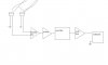
Hi. For the final project of my laboratory course a direction finder circuit has been given. The circuit will work on the principles of phase-interferometry. (2 microphones and a speaker driven with a certain frequency are to be placed so the voltages of the microphones have a phase difference according to the angle of the speaker.) I thought that summing the voltages could be a way to get the phase difference information as the amplitude of the resulting signal will vary according to the phase difference. I suppose there should also be a noise filter and amplifier. To get a clean sinusoidal waveform. Then this output should be measured by a multimeter to get the information to a computer program which should directly give the angle of the speaker as the output. What do you think of this method? Should there be any other elements? In which ordering of the circuit parts i get the best result? (There should be an audio amplifier and a pre-amplifier according to the specifications given.)
Attachments
Last edited:
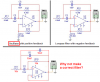
") ) The output voltage peak depends on the phase difference of the two microphones. Do you think with the real components it will work? Is my modeling of the microphones right?
) The output voltage peak depends on the phase difference of the two microphones. Do you think with the real components it will work? Is my modeling of the microphones right?