Continue to Site

Welcome to our site!

Electro Tech is an online community (with over 170,000 members) who enjoy talking about and building electronic circuits, projects and gadgets. To participate you need to register. Registration is free. Click here to register now.

  • Welcome to our site! Electro Tech is an online community (with over 170,000 members) who enjoy talking about and building electronic circuits, projects and gadgets. To participate you need to register. Registration is free. Click here to register now.

Diodes in series...

Status
Not open for further replies.

Phaedrus2129

New Member
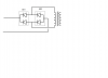
I've got a power supply that I think was designed under the influence of hallucinogenic drugs. It has a +12V output that's using two STPS3045CP Schottky diodes (STPS3045CP Datasheet pdf - POWER SCHOTTKY RECTIFIER - SGS Thomson Microelectronics) in series for rectification. But that's not all. A1 of diode one, and A2 of diode two, are connected to ground. And between the two K terminals there's also a connection to the heatsink of all things, which is itself connected to ground. The remaining terminal of each diode is connected in series with the transformer output.


I have no idea how to even diagram this. What's going on, and what's the effective +12V current output of this mess?
 
That sounds like protection diodes not a rectifier setup.
 
Well, it does rectify. The power supply works, kind of. +12V regulation is horrible even at low loads (like 12.1V at 0A, 11.7V at 10A, for a PSU that claims 40A), and this is with PWM regulation.

So it is rectifying, but not very effectively.
 
The circuit as drawn can only smoke!

Are you sure that the two diode packs are the same part number?
Could it be that one of them is common cathode and the other is common anode?
And the circuit actually looks more like the one in my attachment?

JimB
 

Attachments

  • Strange Diodes.PNG
    Strange Diodes.PNG
    26.1 KB · Views: 425
Last edited:
It may only be a different suffix in the part number for common anode, cathode or a split build. See a BAT54 as example.
 
It'd also be a neat trick to get 40 amps out of a diode rectifier that's only rated for 15 amps.. You'd never see diodes in parallel under that high of a load without some kind of ballast resistors as well.
 
@JimB: That looks more reasonable. SB1 is jammed between the heatsink and the transformer so I can't get a positive ID on the part number. I assumed since it was the same package and started with "STS" that it was the same, but your idea could be the case.

This PSU managed 22A at 11.72V. At 33A one of the diodes popped and shorted after about a minute and the PSU was no more. It's obviously falsely rated. It's made by the Chinese company Golden Tiger, and I've already established that their EE doesn't know how to use Y capacitors properly (putting them in parallel after the bridge rectifier *facepalm*).
 
Last edited:
Agh, just noticed something. What I thought was a connection to the heatsink was actually a resistor buried under the heatsink. Let me get a closer look here.
 
This PSU managed 22A at 11.72V. At 33A one of the diodes popped and shorted after about a minute and the PSU was no more.
Given that the diodes are rated at 15A, they did well to stand up to the abuse you gave them.

JimB
 
What do you make of this:
Not much at the moment, it is difficult to see the tracks between transformer and diodes from that angle.

JimB
 
Show the other side......
 
Sceadwian:

That happened on an arc lamp supply we had. 40 A at 22V with a 40 kV start pulse. Rectifiers were rated at 10 Amps. I got on the phone and the company rebuilt the supply for free. New transformer and diode assembly.
 
Ok, I sat down, and now realizing that what I thought was a connection to the heatsink was actually a resistor, I think I've figured it out. They're not in series, they're in parallel.

**broken link removed**

Derp. Just really confusing with all the other stuff going on on this unit.


So here's the question. With each of those internal diodes capable of doing 15A, what would you say this output is actually capable of? Keeping in mind it burned at 33A.
 
Once it's no longer weird, everyone leaves the thread.
Not exactly, after the none too clear photo and that last schematic of yours which I still think is wrong, I just sort of lost interest.
Weirdness has nothing to do with it.

JimB
 
Your circuit schematic as shown is still weird. One of the diodes in each group has to be reversed so it forms a bridge rectifier. That way you show it the transformer current flow is blocked.

The diodes are rated at 15A so it's not surprising they blew at 33A. For reliable operation I would keep the maximum output current below 15A. (I know each diodes only conducts for a half-cycle but you still should not exceed their average current rating for good reliability.)
 
Status
Not open for further replies.

Latest threads

New Articles From Microcontroller Tips

Back
Top