Continue to Site

Welcome to our site!

Electro Tech is an online community (with over 170,000 members) who enjoy talking about and building electronic circuits, projects and gadgets. To participate you need to register. Registration is free. Click here to register now.

  • Welcome to our site! Electro Tech is an online community (with over 170,000 members) who enjoy talking about and building electronic circuits, projects and gadgets. To participate you need to register. Registration is free. Click here to register now.

Diode voltage drop at low (uA) currents

Status
Not open for further replies.

mdwebster

New Member
Greetings,

I'm looking at powering a tiny PIC from 4 AA batteries, but the max voltage rating on the PIC is 5.5V. Looking at the nominal voltage for fresh AA batteries, the total voltage should be a max of ~6.5V. So I need to drop this a bit for the time when the batteries are fresh and I immediately think of using a diode or two in series with the voltage line.

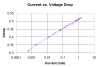
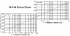
The thing is, thinking further along, this micro is going to spend the vast majority of its life in sleep, drawing only 0.5-1.5uA. (Active mode will draw 1.5mA max) At this current level, for all the diode curves I've examined so far anyway, the diodes won't be dropping their nominal .7V-1V, but only .15 - .25V, which puts me with only a .3V-.5V drop for a pair.

I also don't want to add in a constant current drain resistor to hold the drop at a certain level since this is supposed to be a long-life battery monitor circuit that will remain powered even when the main device is switched off.

My intuition says this might still be okay since the voltage limitation is likely not to cause damage until a significant current is being drawn and when a significant current is drawn, the voltage will drop back down into the nominal range. But I'm not at all certain of this, so I'm here seeking opinions or experience on this.

Thanks for any help or insight,
Mike
 
If you're willing to go with a diode there's not much difference than going with a resistor. They both dissipate energy though the resistor would dissipate more from the I^2. But the resistor may also just not work outright because if the difference between operating and sleep current is large enough, the resistor would have to be large to keep the drop enough voltage during sleep but not small enough to prevent the voltage from dropping too much during operation.

If you're willing to go with a diode, what's wrong with a low drop out linear regulator? It's the same as your diode except it's voltage drop will vary to maintain a fixed output voltage. So the closer your source voltage is to your desired voltage, the less voltage it drops and the less losses you have.
 
Last edited:
You might consider just using 3 cells instead of 4. Many of the Pic chips work fine at a nominal 4.5V level. Simpler is always better ;)

Lefty
 
hi Mike,
Try this, get a high gain npn transistor, connect the base and the collector to the +5V line and the emitter to the load. [circuit]
This replaces the diode.

As a test use a 5M0 [1uA] and 4K7 [1mA] the readings I have using a ZTX651 are: 1uA, Vdp= 0.43V and 1mA Vdp=0.6V

Lets know your test results.:)
 
Thanks for the replies.

I've played with straight-up resistor values and I don't think you can get it where the drop is sufficient at one end and not too much at the other since I want a 1V drop while in sleep at ~1:mu:A = 1M:eek:hm: which won't be able to source the 1.5mA that may be required in active mode.

The four-cell AA is driven by the main part of the device so I can meet a 10-month battery life requirement. The main regulator on the board is a high-efficiency, low-quiescent switching regulator. This thing I'm working on now is just a little always-on (i.e. it bypasses the main power switch) subsidiary circuit that is going to intermittently flash an LED when the batteries start getting low.

I might wind up using an LDO, it's just they're not the cheapest component out there and I haven't hunted one down yet that has less than ~10 :mu:A quiescent draw. Which I could probably live with, but it's my last-choice for the moment...

As to a Collector-Base-connected NPN, I had never thought of that. I'm having trouble visualizing why this would be any different than a simple diode since it's like you're bypassing the B-C diode and just have the B-E one left. I might just breadboard that up this afternoon and see what happens. Thanks for that! :)
 
Man, I still don't get the physics of it, but it seems to work pretty well. I've attached a graph of two separate C-B connected ZTX869's where I varied a potentiometer and took current readings and voltage drop readings for several points and they both follow pretty close to the same logarithmic curve.

Thanks again,
Mike
 

Attachments

  • C-B Connected Diode drop.png
    C-B Connected Diode drop.png
    13.8 KB · Views: 403
mdwebster said:
Man, I still don't get the physics of it, but it seems to work pretty well. I've attached a graph of two separate C-B connected ZTX869's where I varied a potentiometer and took current readings and voltage drop readings for several points and they both follow pretty close to the same logarithmic curve.

Thanks again,
Mike

hi Mike,
In the past I have used this method at higher currents, mA's to 10mA's.

I did have a description of the physics but I cannot find it.

If you ever need a low level negative voltage in a circuit, use this method in the 0V line from the psu.
The voltage before the transistor is about -0.5V relative to the common line.

Does this method meet your requirement.?
 
The graph of the transistor is about the same as the graph of an ordinary diode.
 

Attachments

  • 1N4148.PNG
    1N4148.PNG
    20.9 KB · Views: 306
Audioguru:
It is roughly the same (it's definitely a log curve), but the transistor has a shallower slope (~.32 at 1uA and ~.52 at 1mA). I haven't (so far) been able to find any plain diodes with a slope that shallow.

Eric:
It might well meet my requirements. I need to replicate the results with some cheaper transistors. The ones I messed with are $.70 parts and I'll need three of them to get the required drop. I think I've found some $0.03 parts that should do the same thing (BC850's).

I think I might even tie the low end of the third transistor to ground with a 1M resistor just to keep the voltage drop minimum at a known level. I should be able to afford 5-10uA of leakage.

After looking around a bit, I realized this is a "diode-connected" transistor and I have seen it before in current mirrors and the like. But I'm still not sure what sets that slope. The diode equation is Id=Is[exp(Vd/nVt)-1]. Vd and Vt (voltage across diode and thermal voltage) should be roughly equal between a diode and a diode-connected transistor. I guess that the saturation current (Is) would have the most effect on the slope. There probably are diodes out there that have matching or even shallower slopes, but I get tired of poking around after 30 or 40 spec sheets.
 
This probably isn't appropriate, but thought it worth mentioning... the 5.5 volt Max, is the manufacturers recommended certified level. They guarantee the device will function perfectly. I've used AVR off 4x AA alkaline many times without issue. Also once directly off a 9v (had it on the wrong row of the breadboard), wasn't fresh, but should have been at least 8 volts. I do include a regulator on everything to be supplied with over 5 volts, but haven't killed one yet, the few times I've omitted. Never used a PIC, but have heard a lot more dead-bug stories, compared to AVR. The point is that there is a huge safety margin, 6.5 volts might be still in the safe range. Microchip just excludes itself if there is a problem.
 
The sleep current at the higher voltage is probably going to be higher than the rated one, but resistor diode or regulator you're gonna waste the power somehow.
 
I have many circuits with 74HCxxxx high speed Cmos ICs that use the same Mosfets and spec's as a PIC. They are operating from 6V batteries. The max allowed supply voltage is 7V.
 
The only reason you might want to use a diode is for reverse polarity protection.

Either way, most PICs will run down to 2V so three cells or even two might do depending on your application.
 
Status
Not open for further replies.

Latest threads

New Articles From Microcontroller Tips

Back
Top