Electro Tech is an online community (with over 170,000 members) who enjoy talking about and building electronic circuits, projects and gadgets. To participate you need to register. Registration is free. Click here to register now.
Welcome to our site! Electro Tech is an online community (with over 170,000 members) who enjoy talking about and building electronic circuits, projects and gadgets. To participate you need to register. Registration is free. Click here to register now.
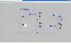
Since V1 is 10V and the voltage at the tap is 5V, and the current through R1 is 10mA, then R1 = E/I = (10-5)/10m = 500Ω
The current through R2 is I = E/R = 5/5K = 1mA.
The current through the diode& RL must be 10mA-1mA = 9mA (Σ currents into node=0)
The voltage across RL is (5-0.7)=4.3V, therefore RL=E/I = 4.3/9m = 478Ω
btw: your assumption that the forward drop across the diode is 0.700V is a little off. At room temperature, a 1N4148 would have a forward drop of about 0.688V. However, the calculations above are based on 0.7V.
This site uses cookies to help personalise content, tailor your experience and to keep you logged in if you register.
By continuing to use this site, you are consenting to our use of cookies.