Continue to Site

Welcome to our site!

Electro Tech is an online community (with over 170,000 members) who enjoy talking about and building electronic circuits, projects and gadgets. To participate you need to register. Registration is free. Click here to register now.

  • Welcome to our site! Electro Tech is an online community (with over 170,000 members) who enjoy talking about and building electronic circuits, projects and gadgets. To participate you need to register. Registration is free. Click here to register now.

Digital Voltmeter!! on Breadboard

Status
Not open for further replies.

remon7

Active Member
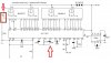
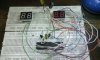
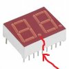
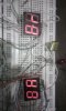
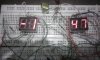
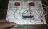
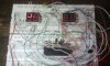
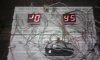
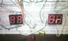
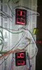
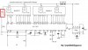
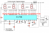
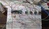
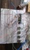
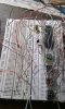
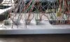
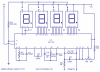
Now i am working on Digital Voltmeter. Already i bought all components for Digital voltmeter. I am using 7 segment display. In 7 segment display.. i am not understand about DP..also i mention in my attachments also i dont have 470n capacitor but i have 47uf capacitor , can i use it there ?
 

Attachments

  • Digital voltmeter circuit diagram.jpeg
    Digital voltmeter circuit diagram.jpeg
    81.4 KB · Views: 1,431
  • 10369592_549929255120089_2664285743655772398_n.jpg
    10369592_549929255120089_2664285743655772398_n.jpg
    82.4 KB · Views: 1,339
Hello remon7,

"DP" stands for "Decimal Point". Connect that pin to ground (through a resistor) to light the "dot".

There is a huge difference between 470nF (0.47uF) and 47uF (it is off by two powers of 10). You will need to find something at least in the range of 470nF.

Regards,
Matt
 
is it DP ?

I suggest you google the part number and find the datasheet. It should have the pinout of the device.

Regards
 
first things that i use 4.5volts and mention that i did not use 470uf capacitor . without this cap i tried to run , but its not working. i dont know whats happen ? how can i check whole circuit ? means checking all components?
 
its not working. i dont know whats happen ?
If you don't use the specified components in the right way of course it won't work!
You can't check all the components (individually) unless you know how each component should perform or what its properties should be. That requires reading the relevant datasheets. Google the part numbers and download the (free) datasheets.
 
I think your tangle of long wires and the many rows of contacts on the breadboard will pickup all kinds of interference. A pcb should be used.
The ICL7107 voltmeter IC is sensitive to interference.
 
I think your tangle of long wires and the many rows of contacts on the breadboard will pickup all kinds of interference. A pcb should be used.
The ICL7107 voltmeter IC is sensitive to interference.

I agree, the ICL devices are very twitchy if the board layout is poor.
 
Yeah finally i have finished my digital voltmeter project, and stuck me. when i plug 4.5volts then it showed me weird number symbol. also when i tried to measure a battery volts then digit symbol also changing, but it does not make any sense , As well as its true that its working, but i could not get where main problem.... ok number 1pic when i used battery for measure. number 2 plug current 4.5volt . without measurements.....normal .. I used ICL7107 somewhere i noticed ICL7106 using for same voltmeter ...so i am using ICL7107. here ICL7106 is not available ..
 

Attachments

  • 1.jpg
    1.jpg
    76.6 KB · Views: 509
  • 2.jpg
    2.jpg
    86.7 KB · Views: 440
  • 3.jpg
    3.jpg
    81.9 KB · Views: 419
  • 4.jpg
    4.jpg
    79 KB · Views: 478
  • 5.jpg
    5.jpg
    76.6 KB · Views: 466
  • 6.jpg
    6.jpg
    65.1 KB · Views: 411
  • 7.jpg
    7.jpg
    7.6 KB · Views: 468
Check your wiring and the datasheet for your display. Are you SURE you used the EXACT parts shown in the schematic? Judging by your previous attempts, I would lean towards "no", in which case of course it won't work. If you did, though, double-check the wiring.
 
in picture there mention ICL 7106 and ICL 7107. But i am using ICL 7107. any problem ?
 

Attachments

  • AAAA (2).jpeg
    AAAA (2).jpeg
    80.7 KB · Views: 532
  • digital panel voltmeter circuit.png
    digital panel voltmeter circuit.png
    225.7 KB · Views: 4,250
The 7106 is designed to drive an LCD display, whereas the 7107 is designed to drive an LED display. How about the LED display part numbers? Are they the same as shown in the schematic?

Could you please post a schematic of YOUR exact setup, with the EXACT part numbers that you are using on your breadboard?
 
i tried to follow new idea about voltmeter. finally its failed again. in 7 segment display nothing shows me.
 

Attachments

  • 10341874_550727615040253_2320463934976978439_n.jpg
    10341874_550727615040253_2320463934976978439_n.jpg
    95.8 KB · Views: 341
  • 10390943_550727625040252_86933699924538160_n.jpg
    10390943_550727625040252_86933699924538160_n.jpg
    92.7 KB · Views: 353
  • 10418212_550727605040254_8677283891974366610_n.jpg
    10418212_550727605040254_8677283891974366610_n.jpg
    94.9 KB · Views: 367
  • eeeee.jpg
    eeeee.jpg
    73.9 KB · Views: 352
  • qqqq.jpg
    qqqq.jpg
    76.1 KB · Views: 341
  • rrrr.jpg
    rrrr.jpg
    76.1 KB · Views: 325
  • wwww.jpg
    wwww.jpg
    80.8 KB · Views: 353
  • 1323621681_31412_FT47549_icl7107-voltmeter-circuit_.png
    1323621681_31412_FT47549_icl7107-voltmeter-circuit_.png
    88.9 KB · Views: 6,396
now i have connected with source but reply is just turn on 7segment display dot light. it does not shows any digit. also i tried to measure battery volts. no output :(
 

Attachments

  • 11111.jpg
    11111.jpg
    60.3 KB · Views: 352
  • 22222.jpg
    22222.jpg
    91 KB · Views: 390
Photographs of your setup with messy wiring really don't help much, I'm afraid. I need you to tell me EXACTLY what components you used, and compare it with the ones shown in the original schematic.

Also, try to neaten up your wiring. Chances are that may be causing some of your issues--it's too confusing to follow, and perhaps there's just a single wire out of place.
 
first things that i use 4.5volts and mention that i did not use 470uf capacitor . without this cap i tried to run , but its not working. i dont know whats happen ? how can i check whole circuit ? means checking all components?
You keep jumping all around and never really answer the questions we ask. If you slow down maybe we can help but you keep changing things.
Did you get the right cap?
Can you neaten up your wiring?
May be just hook up the LSB digit for now untill you can get the chip running.
 
Why don't you use the schematic shown in the datasheet printed by the IC manufacturer instead of using a copy from somewhere that might have errors on it??
 
Status
Not open for further replies.

New Articles From Microcontroller Tips

Back
Top