gramo
New Member
There's a billion (well not quite) circuits out there for Digital to Analogue Conversions (DAC) via Pulse Width Modulation (PWM), but how many of them show you real life results? Consider the most popular that I used to stumble upon; a variation of the below;
**broken link removed**
If you pumped a 50% duty cycle into this circuit, sure it will filter it, but here's what you'll end up with;
**broken link removed**
A rather poor DAC interpretation of the PWM signal. When creating a project for a friend, I ran into this issue and had to find a resolve. There were quite a few considerations, but here's the end result;
**broken link removed**
note the PIC's power supply/OSC are not shown
For great performance, the low-pass filter was designed as a two pole, providing an attenuation of 40 db / decade past its cut-off frequency. The higher PWM frequencies are filtered out by the low-pass filter, thereby reducing the noise in the DAC output. I could ramble on all day with the findings, or simply provide you, the end user, a method that simply works, so lets get started..
**broken link removed**, optimized for 36Khz (so that its out of the audio freq range)
Here's some real life results;
It's a little hard to judge quality from that, so here's some other real life results;
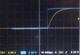
a) Switching from 0% to 100% duty instantly (with short pause in between);
b) Closer look a the Time Constant charge time (image displays a ramp from 0% to 100% duty on a 400uS time base);
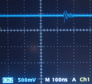
c) The only noise left over is the slight ring from the PIC's PWM signal, extremely clean outside of that (note; the this is a DAC output signal from a 50% duty cycle @ 36Khz. The time base on this test is 100nS)
As per usual, all of the source code and information can be found on the site **broken link removed**
Final Note: Single-supply operational amplifiers with low offset voltage and input bias current specifications are
preferred for driving loads. For cost-effective solutions, however, the operational amplifier can be eliminated, with the
precaution that the load is at least 10 times the combined value of the filter resistors R1 + R2 (in this case, 20*2K = 20K

**broken link removed**
If you pumped a 50% duty cycle into this circuit, sure it will filter it, but here's what you'll end up with;
**broken link removed**
A rather poor DAC interpretation of the PWM signal. When creating a project for a friend, I ran into this issue and had to find a resolve. There were quite a few considerations, but here's the end result;
**broken link removed**
note the PIC's power supply/OSC are not shown
For great performance, the low-pass filter was designed as a two pole, providing an attenuation of 40 db / decade past its cut-off frequency. The higher PWM frequencies are filtered out by the low-pass filter, thereby reducing the noise in the DAC output. I could ramble on all day with the findings, or simply provide you, the end user, a method that simply works, so lets get started..
**broken link removed**, optimized for 36Khz (so that its out of the audio freq range)
Here's some real life results;
It's a little hard to judge quality from that, so here's some other real life results;
a) Switching from 0% to 100% duty instantly (with short pause in between);
b) Closer look a the Time Constant charge time (image displays a ramp from 0% to 100% duty on a 400uS time base);
c) The only noise left over is the slight ring from the PIC's PWM signal, extremely clean outside of that (note; the this is a DAC output signal from a 50% duty cycle @ 36Khz. The time base on this test is 100nS)
As per usual, all of the source code and information can be found on the site **broken link removed**
Final Note: Single-supply operational amplifiers with low offset voltage and input bias current specifications are
preferred for driving loads. For cost-effective solutions, however, the operational amplifier can be eliminated, with the
precaution that the load is at least 10 times the combined value of the filter resistors R1 + R2 (in this case, 20*2K = 20K
Last edited:
