Marks256
New Member
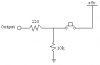
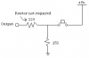
I have numerous 2 pin push button switches(SPST). You know, the ones that have in and out? Just two pins. Ok, now the problem. I would like to use these as digital switches. How would i do that? I have been using the attached schematic, but that doesn't give me an absolute 0. I need a 1 or a 0. Not and NC! Any ideas, or will i need to get a SPDT switch?