yusuf
Member
Hello friends !
I want to join my timer circuit with my logic circuit..
I have attached the complete circuit diagram in my attachment...
Please have a look !
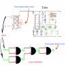
You can see in my circuit diagram , there are two circuit's :
1)logic
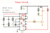
2)Timer
I want the final output pin to connect in the timer circuit...
So, as the final pins (Pin : 10) gows high it should start the timer to run, and if the final pin gows(Pin :10)
low then it should turn off the timer..
At the ouput of the timer a 6v relay is connected to switch a load..
My relay is 6v and has 100ohms coil..
I have given a logic shematics below in my circuit for better understanding...
I am using Cd4093 for my logic work and cd4060 for timer...
Working of Logic :
Pin 1,2 & 5,6 are working as input pin..
Pin 10 will be the final output.
=============
First logic
=============
IF Pin : 1 & 2 goes high , the pin : 3 will gow low and in turn pin 13 is also connected to pin 3 so
Pin 13 will also be low..
If pin 5 & 6 is low, then the pin 4 and 12 will be high..
So the pin 13 is low and pin 12 is high ... so pin 11 will be high and it will also take pin 8 & 9
high , so the final output pin 10 will be low.. and the timer circuit will turn off..
============
Second logic
============
IF Pin : 1 & 2 goes low , the pin : 3 will gow high and in turn pin 13 is also connected to pin 3 so
Pin 13 will also be High..
If pin 5 & 6 is low, then the pin 4 and 12 will be high..
So the pin 13 is High and pin 12 is also High ... so pin 11 will be Low and it will also take pin 8 & 9
Low , so the final output pin 10 will be high.. and the timer circuit will start to run...
xxxxxxxxxxxxxxxxxxxxxxxxxxxxxxxxxxxxxxxxxxxxx
So friends I have made this both circuit and I have tested it seperately ..and it is working but
I dont know how do I connect the logic circuit with timer circuit...
Please help...
Thanks In advance..
I want to join my timer circuit with my logic circuit..
I have attached the complete circuit diagram in my attachment...
Please have a look !
You can see in my circuit diagram , there are two circuit's :
1)logic
2)Timer
I want the final output pin to connect in the timer circuit...
So, as the final pins (Pin : 10) gows high it should start the timer to run, and if the final pin gows(Pin :10)
low then it should turn off the timer..
At the ouput of the timer a 6v relay is connected to switch a load..
My relay is 6v and has 100ohms coil..
I have given a logic shematics below in my circuit for better understanding...
I am using Cd4093 for my logic work and cd4060 for timer...
Working of Logic :
Pin 1,2 & 5,6 are working as input pin..
Pin 10 will be the final output.
=============
First logic
=============
IF Pin : 1 & 2 goes high , the pin : 3 will gow low and in turn pin 13 is also connected to pin 3 so
Pin 13 will also be low..
If pin 5 & 6 is low, then the pin 4 and 12 will be high..
So the pin 13 is low and pin 12 is high ... so pin 11 will be high and it will also take pin 8 & 9
high , so the final output pin 10 will be low.. and the timer circuit will turn off..
============
Second logic
============
IF Pin : 1 & 2 goes low , the pin : 3 will gow high and in turn pin 13 is also connected to pin 3 so
Pin 13 will also be High..
If pin 5 & 6 is low, then the pin 4 and 12 will be high..
So the pin 13 is High and pin 12 is also High ... so pin 11 will be Low and it will also take pin 8 & 9
Low , so the final output pin 10 will be high.. and the timer circuit will start to run...
xxxxxxxxxxxxxxxxxxxxxxxxxxxxxxxxxxxxxxxxxxxxx
So friends I have made this both circuit and I have tested it seperately ..and it is working but
I dont know how do I connect the logic circuit with timer circuit...
Please help...
Thanks In advance..