Electro Tech is an online community (with over 170,000 members) who enjoy talking about and building electronic circuits, projects and gadgets. To participate you need to register. Registration is free. Click here to register now.
Welcome to our site! Electro Tech is an online community (with over 170,000 members) who enjoy talking about and building electronic circuits, projects and gadgets. To participate you need to register. Registration is free. Click here to register now.
...and it's 4-step but not 4-bit
you can use any counter and encode states to what ever you want
how many states are there in total? if it's 3-bit code with zero and odd numbers there would be one more state (7 or 111b).
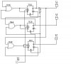
first you should choose a kind of filp-floop
for this case u need three flip-floop .
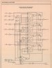
then u sould make a chart that show each case.like this
Qa Qb Qc A B C
0 0 0 0 0 1
0 0 1 0 1 1
0 1 1 1 0 1
1 0 1 0 0 0
Qa,Qb,Qc are the out put of flip flops in last clock pulse and A,B,C are the flip-flops new out put .then reffering to char u select the flip flop input then use Karno chart to simlyfy it and at the end use the gates to desine circute. I will Send u the circute and charts in few hours.
This site uses cookies to help personalise content, tailor your experience and to keep you logged in if you register.
By continuing to use this site, you are consenting to our use of cookies.


")