I want to make a digital alarm clock just for fun.
All my electronics are self taught, so I am pitifully lacking in any solid theory background.
I have in mind a thin design with detachable base to store flat in my computer case while traveling.
The criteria are that it normally run off 120v AC, but keep good time while on battery backup in my suitcase.
Normal timing will be derived from the AC line, but from a clock crystal while on battery.
I want it to automatically adjust the brightness of the display to the ambient light level.
I need at least a 2 inch high led display to be able to read without my glasses at night.
I would like the battery backup to be either two AA cells or a 9V, possibly recharables normally kept on trickle while plugged in.
I was having trouble find something to use for the display when I realized I have a display from an old Radio Shack clock that should work. The attached image is an actual photo of the display with the plastic cover taken off, and the lines cleaned up so I could follow the circuit.
Each segment consists of two led's in series. The segments are connected in groups of two. Half to one ground, and half to another.
The original ran off a 12V transformer which I intend to repackage as a separate unit with short cord to a plug, and long cord to the clock.
I'll have to drive 11 segment groups + colon + am/pm indicator + alarm on indicator + 2 grounds, for a total of 16 lines.
I'll also need at least 5 ports for time setting, enabling alarm, etc, plus 2 for power, 2 for crystal, 1 for ac clock in, 1 for alarm buzzer.
Plus battery charging control, so at least a 28 pin PIC.
I think I can figure out the programming for the PIC, the problem is just with the analog part of the circuit.
The original clock had a single large IC that drove the whole thing with just a few diodes and resistors.
It appears that it drove half the segments with one half the rectified AC cycle, and the other half of the segments with the other half of the rectified cycle.
I can see that a pic is not going to be able to drive this thing directly in the same manner, as there is a relatively high current and lots of segments on at the same time, but I like the simplicity of just driving at the line cycle rate.
It also cuts down on bulky caps and stuff trying to make high current clean DC which the led's don't need.
I can just adjust the brightness by adjusting the on time of each half cycle as needed.
I'm thinking I can adjust the "on" time to compensate for the minimum of 4 segments on at 11:11 o'clock, or 12 segments on at 12:08 to achieve equal brightness between the segments, since I'm not sure how to achieve constant current on a rectified AC waveform. I'm much more of a computer guy than an electronics guy.
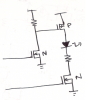
I can see that the low side can be two simple mosfets to ground one or the other set of segments each half cycle, but I don't know enough electronics to know what device to use to switch 12V on the high side of the 14 segments using a PIC running at 3 volts or so.
So, after this long winded dissertation that's my question ---
What type of switch devices to use between the PIC and the high side of the segments?
View attachment seg.jpg
View attachment xxtest.jpg
All my electronics are self taught, so I am pitifully lacking in any solid theory background.
I have in mind a thin design with detachable base to store flat in my computer case while traveling.
The criteria are that it normally run off 120v AC, but keep good time while on battery backup in my suitcase.
Normal timing will be derived from the AC line, but from a clock crystal while on battery.
I want it to automatically adjust the brightness of the display to the ambient light level.
I need at least a 2 inch high led display to be able to read without my glasses at night.
I would like the battery backup to be either two AA cells or a 9V, possibly recharables normally kept on trickle while plugged in.
I was having trouble find something to use for the display when I realized I have a display from an old Radio Shack clock that should work. The attached image is an actual photo of the display with the plastic cover taken off, and the lines cleaned up so I could follow the circuit.
Each segment consists of two led's in series. The segments are connected in groups of two. Half to one ground, and half to another.
The original ran off a 12V transformer which I intend to repackage as a separate unit with short cord to a plug, and long cord to the clock.
I'll have to drive 11 segment groups + colon + am/pm indicator + alarm on indicator + 2 grounds, for a total of 16 lines.
I'll also need at least 5 ports for time setting, enabling alarm, etc, plus 2 for power, 2 for crystal, 1 for ac clock in, 1 for alarm buzzer.
Plus battery charging control, so at least a 28 pin PIC.
I think I can figure out the programming for the PIC, the problem is just with the analog part of the circuit.
The original clock had a single large IC that drove the whole thing with just a few diodes and resistors.
It appears that it drove half the segments with one half the rectified AC cycle, and the other half of the segments with the other half of the rectified cycle.
I can see that a pic is not going to be able to drive this thing directly in the same manner, as there is a relatively high current and lots of segments on at the same time, but I like the simplicity of just driving at the line cycle rate.
It also cuts down on bulky caps and stuff trying to make high current clean DC which the led's don't need.
I can just adjust the brightness by adjusting the on time of each half cycle as needed.
I'm thinking I can adjust the "on" time to compensate for the minimum of 4 segments on at 11:11 o'clock, or 12 segments on at 12:08 to achieve equal brightness between the segments, since I'm not sure how to achieve constant current on a rectified AC waveform. I'm much more of a computer guy than an electronics guy.
I can see that the low side can be two simple mosfets to ground one or the other set of segments each half cycle, but I don't know enough electronics to know what device to use to switch 12V on the high side of the 14 segments using a PIC running at 3 volts or so.
So, after this long winded dissertation that's my question ---
What type of switch devices to use between the PIC and the high side of the segments?
View attachment seg.jpg
View attachment xxtest.jpg
Last edited:
")