Continue to Site

Welcome to our site!

Electro Tech is an online community (with over 170,000 members) who enjoy talking about and building electronic circuits, projects and gadgets. To participate you need to register. Registration is free. Click here to register now.

  • Welcome to our site! Electro Tech is an online community (with over 170,000 members) who enjoy talking about and building electronic circuits, projects and gadgets. To participate you need to register. Registration is free. Click here to register now.

Digital addition using counters and adders

Status
Not open for further replies.

Cable

Member
I am experimenting a circuit for adding two numbers represented by two digital counters and two cascaded 4 bits adders (74hc283). I tested separately with cascaded 74hc163 and with asynchronous 74hc4040 counters and I ended up with the same questions.

I feed one of the counters with a 1 khz com signals and the second counter with 512 hz signals. All signals are well formed square signals.

I use 16hz crystal-controlled time base. The counters count during logic high of the time base that is 1/32 sec or about 31 msec. The counters are reset in the second half of the logic-low of the time base.

When I verify the outputs of the first counter, my prob realizes pulses at some of the outputs and I consider them as logic high. So that the output of the first counter is binary 00011111 to represent the 1khz clk input, almost as expected. The output of the second counter is binary 00001111 to represent the 512 hz clk input also during the 1/32 sec. So far so good.

I feed input a[] of the cascaded adders by the outputs of the first counter and input b[] of the adders by outputs of the second counter. My expectation is to see the correct sum as binary number 00101110 at output s[] of the 8 bits adder, the same way that I see the correct binary numbers at the outputs of the two counters. But instead, I see binary 00111111 as the sum. If I change the clk input of the first counter to 2khz and I leave the clk input of the second counter as it was 512 hz, I see binary number 01111111 instead of the correct sum 01001110 as sum at outputs s[] of the adder. If I change the clk input of the first counter to 512khz like the second counter, I see the correct output of 00011110 as sum at outputs s[] of the adder

Is my expectation to see the correct sum at output s[] of the adder justified while the counters are counting during the logic high of the time base?

If so, why do I get wrong sum?

If my expectation is wrong then how am I supposed to get the right sum while the counters are counting during the logic low of the time base?

Please note that it is not about what kind of counters I am using. It is about the wrong sum no matter which counter I use.

Thank you
 

Attachments

  • counters_adders.png
    counters_adders.png
    132 KB · Views: 342
Last edited:
The "sum" should the running total during the count.

If you are using a logic probe, you will not be guaranteed to see the correct values.
A pulse display on a logic probe could occur on a pin that cycles high then back to low as the count accumulates.

You need to either use an oscilloscope to verify the final count before reset, or change the logic temporarily so the clock is gated off or frozen rather than the counter reset, to give a set of static outputs on the counters and adder.

Or rig up manual clock and reset circuits to you can step the counters and watch the results.
 
I was about to suggest that you check that the carry connections are correct, but I think that rjenkinsgb has the answer.

The LSB of the sum will be changing at 1 kHz and at 512 Hz, so basically changing at 1512 Hz. It will always read as pulses with a logic probe. You need to speed up your reading by using an oscilloscope, or slow down the signal by stopping the clock to take a reading before resetting.

When both counters are running at 512 Hz, both outputs are the same, so when added, the result is always even, so the LSB will always be 0, which is what you are seeing.
 
Thank you for your replies.

About using the oscilloscope suggested by rjenkinsgb, I also checked each output pin by my oscilloscope and I saw pulses of different frequencies at the same outputs of the adders as I saw with the logic probe. Is that how you meant by verifying the final count by oscilloscope? because I cannot think of another way Of using the oscilloscope for checking the final counts and the sum.
 
If it's continuously cycling and resetting as you describe in the original post, trigger the scope off the count/reset signal and look at the final state of each pin as the reset occurs.

Or you could add a single D type latch, clocked by the start of the reset pulse & with a flying lead on the D input that can be connected to any device pin - the counter or adder outputs.

Add a LED & resistor to one the D type outputs and you should get a steady output showing the final state of that pin at the instant the reset happens.
 
Thank you for the tip. As I mentioned in my original post, I can read the expected value at the outputs of the counters at pulsing pins. It is all about the sum at the output of the adders that is not right.

1- So why shouldn’t the output of the adders show correct sum the same way as the counters show correct output at pulsing pins?

If my expectation is wrong for seeing the output of the adders the same way that I see the output of the counters, then I want to try the test method which you suggested. You expect to use the reset pulse for showing the outputs of the counters the moment that the reset happens.

2- Why do you expect the outputs of the counters remain to be seen from the moment that the reset pulse is applied? The data sheet of 74hc4040 shows that when reset is applied all output are set to low (in a matter of nanoseconds).
 
2- Why do you expect the outputs of the counters remain to be seen from the moment that the reset pulse is applied? The data sheet of 74hc4040 shows that when reset is applied all output are set to low (in a matter of nanoseconds).
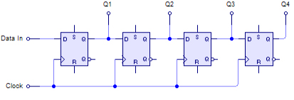
Look at the way any synchronous register works, like a shift register made of D types, as the image below.

The data is latched at the same instant the preceding device is clocked or reset, and the propagation delay through the preceding device means the "old" output is stable long enough to be captured by the next stage.

You must not have any extra gate delays in the clock though - it must be the same signal, or the preceding stage could be delayed by an inverter, if the polarities are wrong; eg. if the new latch needs is positive edge and the reset is negative, add two inverters in line with the reset and take the D clock between the two.

4-Bit_SIPO_Shift_Register.png
 
Just a thought, if you are latching the final result from the adder:

The 4040 is a ripple counter not a synchronous counter so the outputs do not all change at the same time and will be times just after its clocked that the outputs read wrong if captured, as the count steps through all the stages.

Add a delay to the adder result latch signal if you are trying to capture the result, otherwise it will likely be inconsistent.
 
Hi:

So you suggested to "trigger the scope off the count/reset signal and look at the final state of each pin as the reset occurs" and I tried that.

If I understood correctly, I fed the negative of the scope with the reset pulse and I used the positive of the scope to check for the final state of each output pin of the adder. Unfortunately, I see the same result as with the logic probe. That is the output s[] of the adders is 00111111 when the a[] input of the adders is 00011111 and the b[] input is 00001111.

What can be wrong? do you have any other suggestions for me?

Thank you
 
Do you see any variation with any counter output bit as it runs, using the scope and reset sync?

With asynchronous clock sources, I'd expect each counter to vary by one or two counts from cycle to cycle; the result would be a mix of randomly changing counts.

Seeing different counts on the adder result from cycle to cycle could make all appear high to a logic probe, and each high in some cycles on the scope.

And if it were synchronous, 16 & 32 every time, rather than the 15 & 31 you show.

How are you using or capturing the final result? Without a latch to store it at the end of each count sequence, it does not seem to do anything practical?

I'd add an eight bit latch and LEDs to be able to see the result number.
 
So you suggested to "trigger the scope off the count/reset signal and look at the final state of each pin as the reset occurs" and I tried that.

If I understood correctly, I fed the negative of the scope with the reset pulse and I used the positive of the scope to check for the final state of each output pin of the adder.

You need a 'scope with two inputs. There will be a ground connection as well.

The ground of the 'scope should be connected to the circuit ground.

One input of the 'scope should trigger the trace. It is best to have that in the middle of the screen to start with, so you are looking at the point in time just before the reset line goes high
.
scope_point.PNG

The red outline shows where you need to look

Then, you can us the second input of the 'scope to see the value of any point in the circuit just before the reset line goes high.

As a separate point, clock inputs of the 74HC4040s don't need to be gated if you are resetting them.

You have got a cycle which is reset - pause - count. It would be more usual to have reset - count - pause, which would mean that during the pause part, the maximum counts could be read. If you extended the pause to a few seconds, you could read the values with a logic probe.
 
Hi and thank you both for trying to be helpful to me:

I use the final result to compare it with a binary number.
I was first testing with 163 counter but I had the same wrong readings at the output of the adder. So I decided to see what happens if I use the 4040. The sum is wrong with both counters.

And I do have a count, pause and reset pulses. I AND gate the clocks with the time base so that when timebase is logic low no clock input is fed to the counters and the counters pause. I also create a pulse (let’s call is pulse-1) right before the reset pulse is generated. So that the two shoulder to shoulder pulses (pulse-1 and reset pulse) of the same length are generate during the low logic of the time base. The pulse-1 provides plenty of time for capturing the output of the adder when using the oscilloscope.

I am not too concerned about the count of 31 and 32 for example. As rjenkinsgb mentioned, that is solved with synchronous. But I do see variations at t each of the outputs of the adder as a series of pulses at each pin. When I feed the negative of the scope with the reset pulse, I see between 1 and 4 pulses at the outputs. And the sum output is 00111111.
WhenI feed the negative of the scope with the pulse-1, I see more pulse cycles at each of the output pins because the pulse-1 provides more time to capture outputs. And in this case I see output 01111111.
 
Last edited:
So the 01111111 must be the actual sum produced by the adders. The question that remains is why the sum is wrong?
 
I just realized that when I verified the outputs during the entire pause time (the time that the low time base last) or when I grounded the scope instead of just during the pulse-1 time, the actual output is all ones as 11111111.
 
Last edited:
Thank you for your analysis of the problem.

I concluded that the breadboard (BB-32623 from mouser.ca) which I am using is not reliable. For example, intermittently, the time base generator stops working or produces not well-formed signals. However, after I wiggle the capacitor and resistor pins in the section where the time base generator is set up, the generator works again.

All ICs are new and I had duplicates with which I had already tried to troubleshoot the circuit but the ICs seem to be OK.

Another thing that is perhaps unusual is that when the counters and the adder function together, my power supply shows fast variations in the current and power consumption of the circuit. Should I consider that as normal?

I have other components in the circuit and I isolated the two counters and the adder for testing their outputs and I asked questions about my problem in this forum. It is now going to be a pain to dismantle everything and to replace the breadboard but I don’t seem to have a choice.
 
Status
Not open for further replies.

Latest threads

New Articles From Microcontroller Tips

Back
Top