Continue to Site

Welcome to our site!

Electro Tech is an online community (with over 170,000 members) who enjoy talking about and building electronic circuits, projects and gadgets. To participate you need to register. Registration is free. Click here to register now.

  • Welcome to our site! Electro Tech is an online community (with over 170,000 members) who enjoy talking about and building electronic circuits, projects and gadgets. To participate you need to register. Registration is free. Click here to register now.

Designing Bipolar Stepper Motor H-bridge with mosfets

Status
Not open for further replies.

crazybuoy

Member
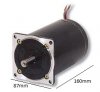
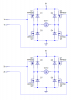
I have a following bipolar stepper motor (same shape) with 3 ohm resistance per winding and want to use it with 12V. I want that the amp requirement of motor should match the amp of H-bridge that it can handle easily without fast heat-up. I have tried to run this motor with L298n but it heats up very quickly.I have also IRFZ44N mosfet, is it suitable to handle current requirement for this motor?

Please suggest me the suitable Mosfet and diode that is suitable for this motor.

Please also tell me the rule of matching current of motor and driver.

Thanks in advance
 

Attachments

  • stepper-motor.jpg
    stepper-motor.jpg
    15.6 KB · Views: 281
  • Bipolar_Stepper_Motor_H-bridge.png
    Bipolar_Stepper_Motor_H-bridge.png
    4.6 KB · Views: 2,458
Last edited:
I = E/R, so if the motor winding resistance is 3Ω, and the supply voltage is 12V, then I=12V/3Ω = 4A per winding. Is the motor rated for 12V to be applied to the winding? I'm guessing that the motor is looking for ~5V per winding. I am not surprised that things seem to be getting too hot...

Is the motor heating up, or is the L298n heating uP, or are both heating too much? The L298n will not stand 2 x 4A without using PWM to reduce the effective winding current.

Before you go building an H-bridge, you need to get complete specs on the motor, and then match the power supply voltage to the motor rating.

If you need to reduce 12V to some lower voltage to match the motor, then you can get a separate switch-mode buck converter to do that, and then run the H-bridge on the lower voltage.

Alternatively, you can use PWM in the H-bridge to reduce the effective "holding" current to the motor windings while retaining the 12V supply voltage. Even the L298 might work with the proper PWM input applied to it.
 
Thanks a lot that was a great reply......

Is the motor heating up, or is the L298n heating uP, or are both heating too much? The L298n will not stand 2 x 4A without using PWM to reduce the effective winding current.

I used L298n with L297. Here only L298n got so much heated up within 30 seconds that I had to disconnect power supply, otherwise it can burn.

The L298n will not stand 2 x 4A without using PWM to reduce the effective winding current.
Even the L298 might work with the proper PWM input applied to it.

Please guide me how can I use PWM with L298n &L297? There are lots of PWM circuits on web. Which one I should use? You can also refer me to any suitable PWM circuit web page.

How about if I build bipolar stepper driver with H-bridge (8 IRFZ44N mosfets) and L297?

Before you go building an H-bridge, you need to get complete specs on the motor, and then match the power supply voltage to the motor rating.

Actually, there is not any label or sticker on motor showing its specs. I only measured winding resistance with volt-meter.
 
It is a two-winding, four-wire stepper?

How much torque are you trying to get out of the motor?

If the goal is to get as much torque as a motor of this size will produce, then here is how I would proceed. Connect the two windings in parallel (combined resistance is 3/2 = 1.5Ω). Connect it to a variable-DC lab power-supply. Start with the supply set to 3V. Confirm that the supply current is I = 3V/1.5Ω = 2A.

Leave the power applied for 30min. Measure the temperature of the motor after 30min. The maximum allowed temperature rise for this type of motor is about 50degC, so if your room temperature is 25degC, the motor should not get hotter than 25+50= 75degC, which would burn your hand. Increase the supply voltage 0.5V at a time, wait 30min, and measure motor temperature again. Repeat until the applied voltage produces a final temperature after 30min of 50degC to 75degC.

Note that this motor would produce P=E^2/R = 12*12/1.5 = 96W of heating if powered with a perfect H-bridge at 12V. I'm guessing that this motor will tolerate only about 20W, so the max applied voltage should be E =sqrt(P*R) = sqrt(20*1.5) =5.5V
 
Last edited:
Status
Not open for further replies.

Latest threads

New Articles From Microcontroller Tips

Back
Top