Hi everyone,
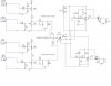
I'm working on simulating an AM modem using circuit maker. My ultimate goal is to create several AM modulators working on different carriers and then sum them up with a summing amplifier in order to be fed into an optical transmitter ( IR LED for instance).
On the receiving side the signals are separated by active BPF and each demodulated by a proper envelope detector. Currently I'm facing these problems:
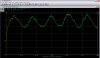
- The envelope detector is simply a diode with an RC circuit where
Carrier Period < ζ = RC < Message Period. I've tried several values for R and C but the result is unsatisfactory (Figures "Fig_1" and "Demod").
- After I added the summing amplifier I couldn't get a good result at the demod - perhaps impedance issues?
I've attached all the circuits and I really need help in determining the R and C value for both envelope detectors.
Note: first AM modulator has a carrier of 23.2 KHz and the second of 10.7 KHz, message for both is a sine of 25 Hz.
thx for all future help.
BR
I'm working on simulating an AM modem using circuit maker. My ultimate goal is to create several AM modulators working on different carriers and then sum them up with a summing amplifier in order to be fed into an optical transmitter ( IR LED for instance).
On the receiving side the signals are separated by active BPF and each demodulated by a proper envelope detector. Currently I'm facing these problems:
- The envelope detector is simply a diode with an RC circuit where
Carrier Period < ζ = RC < Message Period. I've tried several values for R and C but the result is unsatisfactory (Figures "Fig_1" and "Demod").
- After I added the summing amplifier I couldn't get a good result at the demod - perhaps impedance issues?
I've attached all the circuits and I really need help in determining the R and C value for both envelope detectors.
Note: first AM modulator has a carrier of 23.2 KHz and the second of 10.7 KHz, message for both is a sine of 25 Hz.
thx for all future help.
BR