micr0man
Member
Hello everyone,
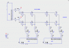
I am designing an LED matrix which will be a 10 row 40 column display. The 10 row is a preference
The 400 5mm red LED's were brought in bulk in a sale and no datasheet was given so I am guessing a forward voltage of 2 volts and I would like to run them at 15ma.
For the display i shall be running a row scan so will use some high power N channel MOSFET's. for the columns i shall be using some shift registers powering some PNP transistor arrays.
I am in the design process thinking about how i will do things so i have not thought about specific part numbers but the micro controller i will use will be either the PIC18F4620 or the PIC18F4220
My question is this,
How is the series resistor's ohmage and wattage calculated for each column. I understand that the LED will only be lit 1/10 of the time so I can increase the current but is it by 10 times.
I have also been told that using a constant current source would be better to be used because otherwise i may get unevenness it the brightness of the LED's. Is this true and would it have much of a benefit. I can see it being much more expensive considering i am keeping a very low budget
Thank you very much for reading,
David