Continue to Site

Welcome to our site!

Electro Tech is an online community (with over 170,000 members) who enjoy talking about and building electronic circuits, projects and gadgets. To participate you need to register. Registration is free. Click here to register now.

  • Welcome to our site! Electro Tech is an online community (with over 170,000 members) who enjoy talking about and building electronic circuits, projects and gadgets. To participate you need to register. Registration is free. Click here to register now.

Design Step Down dc-dc converter

Status
Not open for further replies.

macmmt

New Member
Hello,

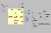
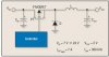
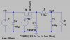
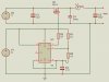
I’m designing a step-down dc-dc converter. The input voltage is 7V and the output voltage is 2V. The control is done through PWM with an IC 555. The switching frequency is 300kHz.

I have tried to make it work, but it doesn’t. I would like, you help me checking it to find any error. Please let me know what is happening with this circuit. I have attached the circuit design.

Thank you very much for your help.
 

Attachments

  • Buck Converter.jpg
    Buck Converter.jpg
    104.1 KB · Views: 7,007
Last edited:
Sorry i uploaded the wrong image. I do generate the pulses with 555 but when I join the output to the MOSFET, the converter doesnt work.
 
The MOSFET is N so it takes a positive voltage to turn it on. The gate needs to be 5 to 10 volts above the source. The 555 needs a higher supply voltage. Or change it to a P MOSFET and set the source on the positive supply.
 
Most SMPS that I have seen have voltage sense resistors on the output. This sense voltage to fedback to the PWM control to control the PWM to keep the voltage regulated.
 
You could use a part made to do what you want. Example LT3470. The output voltage is set by R1 & R2. Your poor little 555 does not regulate the voltage.
 

Attachments

  • image3.jpg
    image3.jpg
    149.1 KB · Views: 1,264
What I have to do, is to implent the circuit that is attached.
As the control circuit I'm using the 555. I have set a higher voltaje but it doesnt have any effect.
 

Attachments

  • Circuit.jpg
    Circuit.jpg
    17.8 KB · Views: 1,863
I have been changing the MOSFET since it doesn't work and trying diferent ways.
Which Mosfet will you work with? and How would you implent the control circuit?
 
OK…. Here is a circuit with both a P and an N MOSFET. I chose it so you can see how to use each. The N is sitting on ground. If pulls a node to ground when it’s gate is positive. The P is on the positive supply and pulls up when it’s gate is pulled negative. Note your last circuit is wrong the P MOSFET is backwards.
 

Attachments

  • Image1.jpg
    Image1.jpg
    116.4 KB · Views: 1,194
Thanks I understood that part. Now the question is: If I use the N-Mosfet and the 555 in my ciurcit, would the converter work?? or should I include another element?
 
source of Q1 is at ground when off. (-0.7 volts)
source of Q1 is at 7 volts when on. (6.9)
gate of q1 should be at 12 volts when on.
L1 is tooooo small 2.91uH is like a wire try 291uH or 2.9mH.
R3 is too large 10k---->220 ohms
V1 9 volts ---->12 volts.
 
Sometimes it is needed to use optocouplers to separate the power circuit from the control circuit. Do I need them in this design?
 
no opto
Pink line shows the currentin the inductor.
Blue line is gate voltage 12/0
Light blue is source voltage. 7/-0.7
Output about 4 volts at 50%

V1 is 7 volts.
V2 is what the 555 could be doing. 12 volts when on, 0 volts when off, delay of 1nS, raise time=1ns, fall time =1ns, ontime=5uS, frequency=1/10uS = 100khz.
 

Attachments

  • Image2.jpg
    Image2.jpg
    161.6 KB · Views: 762
  • image3.jpg
    image3.jpg
    65 KB · Views: 821
For 7V in and 2V out and a N channel MOSFET's you need a ~28.57% duty cycle. With the 555 as wired, you can't get less than 50% on, so it won't work. If you add a diode across "R2" you can now have a faster "discharge" than "charge" time. If you like, the "CV" pin can be used for feedback, but the switching frequency will move around with line and load.
 
Status
Not open for further replies.

Latest threads

New Articles From Microcontroller Tips

Back
Top