Electro Tech is an online community (with over 170,000 members) who enjoy talking about and building electronic circuits, projects and gadgets. To participate you need to register. Registration is free. Click here to register now.
Welcome to our site! Electro Tech is an online community (with over 170,000 members) who enjoy talking about and building electronic circuits, projects and gadgets. To participate you need to register. Registration is free. Click here to register now.
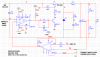
From a quick look it appears the circuit will functionally work.
But you will need compensation in the error amp for stability. The output filter L1 and C4 form a resonant tank circuit that causes a large phase shift in the feedback. Without compensation, this phase shift will cause positive feedback and oscillation near the resonant frequency.
If you make it current mode control, you will have an easier time with the loop. The double pole from the LC goes away and you can use simple type 1 compensation.
If you make it current mode control, you will have an easier time with the loop. The double pole from the LC goes away and you can use simple type 1 compensation.
That is true. But then you need to add a current sensor in the switching circuit such as a current transformer, or another winding on the inductor. So the tradeoff is one complexity for another.
This site uses cookies to help personalise content, tailor your experience and to keep you logged in if you register.
By continuing to use this site, you are consenting to our use of cookies.