Continue to Site

Welcome to our site!

Electro Tech is an online community (with over 170,000 members) who enjoy talking about and building electronic circuits, projects and gadgets. To participate you need to register. Registration is free. Click here to register now.

  • Welcome to our site! Electro Tech is an online community (with over 170,000 members) who enjoy talking about and building electronic circuits, projects and gadgets. To participate you need to register. Registration is free. Click here to register now.

Delay 16f88 assembly language

Status
Not open for further replies.

oualau

New Member
Hi all, I am new in this and definitely not good in this.

I have read a topic about this, but I am still not quite sure about the whole delay thing...
https://www.electro-tech-online.com/threads/tmr0-1-second-delay-help.27669/

I want to make a servo controller using 16f88.
there are few things that I would like to make sure of:
1. Is it possible to use external clock (I'm using 4MHz crystal oscillator) together with TMR0? I am planning to use TMR0 for delay purpose.
2. Since the maximum number to put into TMR0 is 256, what should I do if I want to make a delay of 1 hour?

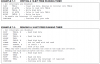
If it is possible, please give me an example or two of simple delay program.

Any help will be greatly appreciated.

Thank you.


Regards.
 
Hi,

1. Is it possible to use external clock (I'm using 4MHz crystal oscillator) together with TMR0? I am planning to use TMR0 for delay purpose.

Why bother using a crystal when the chips got a perfectly good internal oscillator ?
Some people say its not very accurate but you are talking tiny amounts.

2. Since the maximum number to put into TMR0 is 256, what should I do if I want to make a delay of 1 hour?

You do not say if your program will be doing other stuff for the hours delay, but for such a long period you are amost talking about a Real Time Clock.See the 88s datasheet Timer1 for details.
 
hi everyone, thanks for the reply.

but as I have stated above, I am completely new to this thing and the only material that I have is for TMR0...

If you could guide me about TMR1 or TMR2 I will greatly appreciate your help.


Regards
 
Hi, its all in the data sheet. Heres a picture form the datasheet telling you how to configure Timer 1
 

Attachments

  • Untitled.png
    Untitled.png
    81.8 KB · Views: 377
oh, I am very sorry, it is not delay for an hour, but doing the same thing for an hour.

I want to write a program for 16f88 using assembly language to control a servo and I want the servo to stay at its position for an hour.

Any kind of help will be greatly appreciated.
 
mr wond3rboy, I am very confused about the HI_BYTE and LO_BYTE words. are they just word to represent any value that I can assign to them or are they a keyword (HI_BYTE and LO_BYTE) represent a fixed value.
and also, what are TMPH and TMPL? Can I assign any memory location to TMPH and TMPL?
 
Last edited:
Hi,

Well you need a Timer for one hour so you will have to use one of the chips hardware timers and the ISR as mentioned earlier.

Controlling a sevro is readily done with a Pic , but for a beginner understanding how to do it and write the code might be a bit too much for you at the moment.

Think you might be better starting off as we all do with the proverbial flashing led and building up your assembler experience before you try and do your full project.
Nigel has this tutorial and he and others in the forum can easily help if you get stuck.


Out of interest, you say you are using the 16F88, a good little chip, but do you have a dev board / programmer or are you using a simulator ?
 
mr wond3rboy, I am very confused about the HI_BYTE and LO_BYTE words. are they just word to represent any value that I can assign to them or are they a keyword (HI_BYTE and LO_BYTE) represent a fixed value.
and also, what are TMPH and TMPL? Can I assign any memory location to TMPH and TMPL?

The HI_BYTE and LO_BYTE are values you put in to the Timer registers that determine your delay(you must be doing that with Timer 0 as well).

TMPH and TMPL are simly names of memory locations. You can refer to memory locations by names using the EQU directive.

Download the 16F88 datasheet and go through the Timer 1 Section.
 
Here is a simple 1 hour delay. It also flashes a LED very briefly to show the delay is working:

HTML:
;x1min  - 1 minute delay
        
x1min    movlw    .78                    
    movwf    xmin_3        
_1min    goto    $+1                
    goto    $+1
    goto    $+1
    goto    $+1        
    decfsz     xmin_1,f
    goto     _1min
    decfsz     xmin_2,f
    goto    $+2
    goto    $+3    
    bcf    gpio,5    ;give the LED illumination-time    
    goto     _1min
    decfsz     xmin_3,f
    goto    $+2
    retlw     00            
    bsf        gpio,5    ;flash LED
    goto    $+1                
    goto    $+1
    goto    $+1
    goto    $+1            
    goto     _1min            
                
x60mins    movlw    .60
    movwf    temp_60
    call    x1min
    decfsz    temp_60,1
    goto    $-2
    retlw    00
 
Last edited:
At the beginning of your program, give a name to all the files you will be using in your program.
Here are some names: You can give a file any name you like. But give it a name you can easily recognise - and try to use it in only one sub-routine. Especially if it is a file that holds a value during the calling of a number of sub-routines.

HTML:
;***************************************************
; variables - names and files
;***************************************************


temp1        equ 20h    ;
temp2        equ 21h    ;
temp3        equ 22h    ;
temp4        equ 23h    ; 
_beepA        equ 24h    ;for beep tone
_beepB        equ 25h    ;for beep tone
_flash        equ 26h ;for flashing the LED
_potA        equ 27h ;holds value 1-10 for x10minutes
_potB        equ 28h ;holds value 1-10 for minutes
_loops        equ 29h ;
temp        equ 2Ah ;
del_x        equ 2Bh ;
del_y        equ 2Ch ;
xmin_1        equ 2Dh ;
xmin_2        equ 2Eh ;
xmin_3        equ 2Fh ;
temp_10        equ 30h
retlw means: return to where the sub-routine was called and if the sub-routine creates a value from 1 to 0ffh, it can be placed in "w" register and the value can be used in the Main routine.
It just saves creating another file is a value is created in the called sub-routine. In most cased the micro returns with 00h in w.

goto $+1 increases the pointer but takes 2 cycles, whereas "nop" requires only 1 cycle.

The Main part of your program calls x60mins and this sub-routine loads .60 (decimal sixty) into a file. This sub-routine then calls x1min and it takes 1 minute for the sub-routine to execute. During this time a LED is turned on approx every second for a very short period of time to let you now the delay is executing.
The 1 minute delay returns to x60min sub-routine and the counter is decremented from 60 to 59.
Eventually 60 minutes is up and the program counter returns to Main.

The delay has nothing to do with working a servo.

In Main, you send a brief pulse to the servo (with the correct value of HIGH and LOW) and the servo moves to this position.
You then go to the Delay sub-routine for 1 hour and the servo remains in the same position.
The program then returns to Main and you send another pulse to the servo to change its position.

THE SERVO

A servo module consists of a motor and gearbox, with a PC board containing the electronics to drive the motor in clockwise and anticlockwise direction. The electronics also detects the width of the incoming pulse to drive the motor to mid-position and also other positions.
The motor is connected to the positive rail of the supply via a bridge of transistors within the servo and the red and black wires from the module are taken to the positive and negative of a battery to provide the current to drive the motor.
The third lead (white) is the control line and this is taken to the micro.
This line needs a pulse and the maximum repetition-rate accepted by the servo is every 18mS - it will accept a longer timing between pulses. This is the timing between pulses, the actual pulse-width is very short, between 0.9mS and 2.2mS.
If the pulse is less than 1mS duration (wide) the servo will travel fully in the anticlockwise direction.
If the pulse is 2mS, the servo will travel in the clockwise direction.
If the pulse is 1.5mS, the servo will travel to the mid position.
If the pulse is between these values, the servo will travel to a pre-determined position.
If the time between pulses is longer than 18mS, the speed of rotation will be decreased.


Last edited:
Dear mr. colin55, you said: "In Main, you send a brief pulse to the servo (with the correct value of HIGH and LOW) and the servo moves to this position.
You then go to the Delay sub-routine for 1 hour and the servo remains in the same position.
The program then returns to Main and you send another pulse to the servo to change its position."

From what I have learned, the servo has to receive the same signal every 20ms to retain in its position. For instance, if I want to stay in mid position for 1 second, then I will have to send a HIGH of 1.5ms and a LOW of 18.5ms 50 times. (the total length is 20ms, 20ms * 50 = 1 second). Please correct me if I'm wrong.
 
From what I have learned, the servo has to receive the same signal every 20ms to retain in its position. For instance, if I want to stay in mid position for 1 second, then I will have to send a HIGH of 1.5ms and a LOW of 18.5ms 50 times. (the total length is 20ms, 20ms * 50 = 1 second). Please correct me if I'm wrong.

hi,
You are correct, without the 20mS refresh the servo will relax into a non holding state.
 
Servos are not "maintained" during the rest period. It is very difficult "to drive a servo in reverse" Get yourself a servo and do some experimenting.
 
I'm sorry, mr colin55, but I don't quite understand about servos are not maintained during rest period. As for driving servo in reverse, I heard there's a modification that has to be done on the servo to achieve that.

so, colin55, you are saying that servo only need to be controlled once and without any pulse it will stay there, isn't it?

and also, what does cblock command do?
if it is the same as EQU which assigning names to memory locations, where does it start?

regards.
 
Last edited:
It will stay in position if you don't have a large force trying to turn the output shaft. You really shouldn't "drive the servo in reverse" by trying to turn the output shaft.
 
now then, that's interesting.... quite different from what I have learnt. I will have to do some experiments to verify this.
I will come back with the program once I have written it, just a simple one. I am very new in this and I don't have the confidence in it.

and also, what does cblock command do?
if it is the same as EQU which assigning names to memory locations, where does it start?


regards.
 
Last edited:
Cblock defines the start of the RAM addressed and is used to name variable registers

E.g. in the pic16f88 in bank0, the free RAM addresses begin at 0x20.
Therefore I can define my registers by doing:

cblock 0x20 ; start at 0x20
Register1 ; defined as 0x20
Register2 ; defined as 0x21
Register3 ; defined as 0x22
endc ; tells assembler we are done
 
Status
Not open for further replies.

Latest threads

New Articles From Microcontroller Tips

Back
Top