Continue to Site

Welcome to our site!

Electro Tech is an online community (with over 170,000 members) who enjoy talking about and building electronic circuits, projects and gadgets. To participate you need to register. Registration is free. Click here to register now.

  • Welcome to our site! Electro Tech is an online community (with over 170,000 members) who enjoy talking about and building electronic circuits, projects and gadgets. To participate you need to register. Registration is free. Click here to register now.

debouncing??

Status
Not open for further replies.

Bavananth

New Member
Hi all!

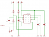
When I apply pulses from signal generator the 74HC163 counter counts properly. But I tried to give pulses from an on/off switch (to simulate an environment where I have to count pulses coming out of another circuit)It jumps to a wrong value.(May be due to the bouncing at the switch) so I used an RC circuit to drag the pulse time such that all vibrating pulses vanishes inside the pulse. I have tried it with many R and C values. But It dint work. What to do now? I have attached my diagram please go through that.

Thank you!
 

Attachments

  • debouncing swich2.JPG
    debouncing swich2.JPG
    30.9 KB · Views: 173
Here's a good reference and another, 555-based option. Is there a reason you need to stick to the RC design you have?

John
 

Attachments

  • debouncing_Ganssle.pdf
    472.2 KB · Views: 396
  • 555pulse.png
    555pulse.png
    6.4 KB · Views: 230
You should look at Debounce Circuit on Google.
Your diode stops the input of the 74HC161 from going low so it will be high all the time until interference drives it low.
 
Hi jpanhalt, That is a wonderful article about debouncing switches. But those diagrams will be useful for switches but not for my circuit. i have attached my diagram more clearly.

Caps dint work. Counter values vibrates when the pulses come. I want the distorted pulses to be a smooth pulse.

???????:(
 

Attachments

  • circiut.JPG
    circiut.JPG
    37.2 KB · Views: 165
An on and off frequency works fine on a breadboard.
A high frequency analog circuit gets messed up due to the high stray inductance and capacitance of a breadboard.
 
I don't see any reason a switch debouncer wouldn't work. For example, in the circuit I posted, pulling Pin1 of the switch low (i.e., the high-low transition in what you drew) creates a single pulse of width defined by the 555. It cannot be retriggered until the switch is re-opened (i.e., the high in your signal). Other latch debouncers act similarly.

It is true you get a pulse on LOW, rather than HIGH, but that is a simple thing to invert.

Is the signal you are counting regular? That is, are the high and low times regular are does one or both vary? In the 555 debouncer, for example, the low times can be whatever you want them to be, but the high pulse is fixed (before inversion). The flip-flop debouncers don't have that restriction.

John
 
Not regular pulses. I'll try those NE555. other one(SR doesn't look suitable for my applicastion. In which pin I apply my pulse stream? It would damage my generator circuit.)
 
Bavananth said:
Not regular pulses. I'll try those NE555. other one(SR doesn't look suitable for my applicastion. In which pin I apply my pulse stream? It would damage my generator circuit.)

hi Bavananth,
When you build your 555 debouncer, keep the 555 output voltage the same as the voltage powering the HC163.
That is power the 555 from the same rail as the HC163. OK.:)
 
Bavananth said:
Not regular pulses. I'll try those NE555. other one(SR doesn't look suitable for my applicastion. In which pin I apply my pulse stream? It would damage my generator circuit.)

The 555 circuit will give a low period (after inversion) of fixed width.

The input is at the switch leg being pulled to ground.

John
 
After a complete analysis I found out the real problem. I used NE555 circuits to remove noises and vibrations. But still the problem is there.(Counter bounces whenever my circuits pulse is fed. But direct signal generator connection works perfectly)

So I Applied A big capacitor and resistor between the generated pulse and counter, to delay(slowly fade) the transition such that I can observe what happens when transition occurs.

I observed that It occurs It occurs whenever It passes 2V. (Either in the down ward direction or upward directin )

So now I can't get the point of it.

Why does this problem occur?
 
What happens if you put the resistor in series with the signal and before the capacitor like in the attached?
John
 

Attachments

  • DEBOUNCER2.PNG
    DEBOUNCER2.PNG
    4.1 KB · Views: 163
A 555 causes a 400mA supply current spike each time its output switches. A Cmos 555 causes a much lower spike.
The datasheet for the LM555 recommends two supply voltage bypass capacitors to absorb some of the spike it produces.
 
Hi, It worked at last. I used an active filter(using UAF42) and NE555 circuit(**broken link removed**) but replaced the 1uF with a 47uF. Transition was very slow but it worked. counters dint blink. Thank you so much everybody. I really appreciate your help. Thanks again.
 
Status
Not open for further replies.

Latest threads

Back
Top