Electro Tech is an online community (with over 170,000 members) who enjoy talking about and building electronic circuits, projects and gadgets. To participate you need to register. Registration is free. Click here to register now.
Welcome to our site! Electro Tech is an online community (with over 170,000 members) who enjoy talking about and building electronic circuits, projects and gadgets. To participate you need to register. Registration is free. Click here to register now.
Ganssle actually shows a few hardware solutions, a RC being just one of a few, Colin I assume your method included a resistor as well to setup the charge/discharge time.
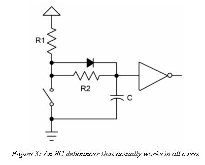
According to the article Ganssle suggested this RC method (added diode) : The article explains the math to calculate the R and C values.
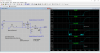
The bounce interval is increased in 50ms steps. In Step 1 the switch bounces for 50ms and in step 4 200ms.
In step 4 you can see the output bounce. Of course, this is a crummy switch if it bounces for 200ms.
"The diode is an optional part needed only when the math goes haywire. It's possible, with the wrong sort of gate where the hysteresis voltages assume other values, for the formulas to pop out a value for R1 + R2 which is less than that of R2. In this case the diode forms a short cut that removes R2 from the charging circuit. All of the charge flows through R1. The previous equation still applies, except we have to account for drop across the diode. Change Vfinal to 4.3 volts (5 minus the 0.7 diode drop), turn the crank and R1 pops out."
Need for a diode in that circuit is the exception, not the rule for RC debouncers according to Ganssle. A link to Ganssle's articles was provided early in the thread, so there was no need to repeat that circuit, except by way of explanation. Unfortunately, Mikebits didn't provide any explanation for the diode in the generic circuit he recommended, nor did he give sufficient information to calculate whether the diode was needed. My question was simply asking him for clarification of his choice so others could understand the need for added complexity should it arise.
I did not realize nor intend such a simple question to be offensive, but apparently it caused such great offense that ETO decided to hide my post to protect unwary readers. I apologize for offending you and gophert and any others. That was not my intent.
What I cannot justify is your snarky response for such a simple question. Is your knowledge so profound that a simple question like I posed offends you?
Unfortunately, Mikebits didn't provide any explanation for the diode in the generic circuit he recommended, nor did he give sufficient information to calculate whether the diode was needed.
Why would I need to provide explanation, I simply showed one of the hardware configurations mentioned in the article you linked to which I had stated. What prompted me to do this was that Colin told the OP all he needed was a cap across a switch, which left out some of the components which I think are needed. In fact I take your response to my last post #4 as being snarky. You did the same thing to me on another thread I made about a website that compared vendor prices such as Mouser vs Futurelec, Digi-key etc. I posted the info to help others and what I got from you was some snotty response. It seems that if you take a disliking to someone, you then go out of your way to make that person look foolish.
I think I get what you mean, Pommie did some code for the junebug and servo's, in it there was a routine for telling which button was pressed, while it wasnt a debounce routine it did the job well for debouncing.
I might try and find it, it was for working out which button was pressed (IIRC) but in doing so it also debounced by default because of how it was written. I thought you taught Mr T?? Or maybe I dreampt that?
Both. If you have a problem with bouncing switch, you can fix it in hardware or in software. There are many solutions to both cases.. just google and pick one that you are comfortable to implement in your system.
I have never had a system where button bounce is a problem.. never written a debounce routine. Never written code where multiple butten presses would be a problem. There are no single "best way".. there are bad ways. You can tell a bad way from a good way very easily. The bad way does not work.
If you are designing a switch debounce circuit you need to consider the following factors:
(1) switch contact minimum current
Depending on the switch contact material, a cleaning current may be required- generally gold and carbon/composite contacts are suitable for zero current operation.
(2) Switch contact maximum current
It is unlikely that this value would be exceeded, but where a capacitor is connected across a switch, especially a high value capacitor, a large instantaneous current can flow and damage the switch contacts. With a low current switch this normally means punching through the gold flash on the contact to expose the non zero current material under the gold flash.
(3) maximum rise and fall time of input signal to logic family input
For all logic families, with the exception of the Schmidt trigger input types, there is a maximum rise and fall time which must not be exceeded. The reason for this is that between input logic voltage levels the chip is an amplifier which can oscillate and generate multiple output pulses and, in the extreme, destroy itself. For this reason only Schmidt input logic devices should be used with integrating (capacitor) debounce circuits. So for example, in the OP the integrating debounce switch should not be connected directly to the 74LS90 counter chip. Instead a Schmidt input device, 74LSxx14 or 74xx132 for example, should be used between the counter clock input and the switch. Care is also needed with software debounce schemes to ensure that the switch input to the system does not cause hardware problems. In most cases a mechanical switch does not generate an edge fast enough for most logic families.
(4) Behavior of debounce circuit with different button press duration
The clock output should be defined for all combinations of switch on/off durations
(5) Behavior of debounce circuit at power turn on and turn off
The circuit should not generate spurious clocks at power turn on or turn off.
(7) Flexibility
(7.1) Should be suitable for a single contact switch and not require change over switch as with some debounce circuits and should be suitable for both make and beak switches
(7.2) Up (supply rail) and down (0V) switching should be catered for.
(7.3) It should be possible to configure for a positive edge or negative edge clock output.
With good design the integrating debounce circuit will be adequate for most applications but item (1), (2), and (3) are not properly addressed on many debouce circuits, especially on the net.
Other debounce circuits for critical applications are:
(1) Schmidt trigger timed
(2) logic
(3) clocked
(4) dedicated chip (best where many switches are required)
This may seem strange but one of the least reliable and troublesome circuit function, in my experience, has been clock input switches. In one instance the spring loaded button on a piece of test equipment flew off and hit the test engineer in the eye- luckily it didn't do much damage.
This site uses cookies to help personalise content, tailor your experience and to keep you logged in if you register.
By continuing to use this site, you are consenting to our use of cookies.