Continue to Site

Welcome to our site!

Electro Tech is an online community (with over 170,000 members) who enjoy talking about and building electronic circuits, projects and gadgets. To participate you need to register. Registration is free. Click here to register now.

  • Welcome to our site! Electro Tech is an online community (with over 170,000 members) who enjoy talking about and building electronic circuits, projects and gadgets. To participate you need to register. Registration is free. Click here to register now.

DC PWM control with polarity change

Status
Not open for further replies.

FireAce

New Member
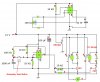
DC PWM control with polarity change at the push of a momentary button, this circuit is for whosoever will. I put together two different circuits to make one, with slight modifications.

The 555 PWM circuit can be found here, I really like this circuit, it performs very nice on my N Scale locomotives.
**broken link removed**

I cant seem to find the link for the momentary on/off circuit, but its pretty much as you see on attachment.

Enjoy!
 

Attachments

  • PWM circuit with direction change.jpg
    PWM circuit with direction change.jpg
    207.7 KB · Views: 521
OOOPS, left out a MAJOR component, lol, need to add 0.01uf NON Polarized capacitor between output #6 and ground, on the upper 555 timer. Sorry bout that.
 
Put the relay between the collector and ground on the PNP transistor, with the emitter to +12v.
Ken
 
Last edited:
Hi Moffet, why is that? I will have to say, although the circuit works fine the way I have it, it actually didnt simulate in Yenka ( the sim program I drew it up in). I pretty much have NPN transistors figured out, but I dont use PNP's a whole lot. Thanks
 
You are configuring the NPN transistor as a common-emitter amplifier, which has voltage gain, will saturate, dissipating minimal power, and fully power the relay.
You are configuring the PNP transistor as a emitter-follower amplifier, which does not have voltage gain, will never saturate, dissipating excess power, and not fully power the relay.
It might work, but not optimum with the same components. If you change the PNP to a common-emitter configuration, it will work as the proper compliment to the NPN.

Or drop the two transistor, two resistors, two SPDT relays (and diodes)...and drive a DPDT relay (w/diode) directly off of the 555. Assuming the 555 can handle the relays coil current. If not, add the NPN and resistor back in.

Ken
 
Last edited:
Status
Not open for further replies.

Latest threads

New Articles From Microcontroller Tips

Back
Top