Continue to Site

Welcome to our site!

Electro Tech is an online community (with over 170,000 members) who enjoy talking about and building electronic circuits, projects and gadgets. To participate you need to register. Registration is free. Click here to register now.

  • Welcome to our site! Electro Tech is an online community (with over 170,000 members) who enjoy talking about and building electronic circuits, projects and gadgets. To participate you need to register. Registration is free. Click here to register now.

DC Power Supply PCB

Status
Not open for further replies.

pixnum

New Member
Dear Friend,

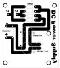
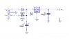
I have design a DC Power Supply (Bridge Type) for my audio amplifier. Please check my PCB design as an attachment file and tell me how I can make more smooth DC supply. Also tell me whether my design is right or wrong and give me some light on it.

Thank you,

Have a good day !
 

Attachments

  • Bridge Type DC Power Supply.jpg
    Bridge Type DC Power Supply.jpg
    24 KB · Views: 1,673
That's a pretty basic power supply, completly unregulated. To get the output as smooth as possible use the largest electrolytic capacitors you can fit on the board that work at the rated voltage. What kind of voltage's / currents are you working with? You may be able to just tack on a linear regulator to give you regulated output which will make your amp much happier.
 
Thank Sceadwian !

I like to use 2200uf/ 63v capacitor and I have also in mind that how I can get 3volt dc from LM7805 regulator from this pcb. Can you give me some light ?
 
You really need to provide more information on what you're trying to do. You still haven't said what voltage the AC in is, or where that AC is coming from, or any idea of what kind of output voltage you want except the 3volt DC, which is not possible because the 7805 is a fixed 5 volt regulator.
 
TRY 3 SILICON DIODES AT THE OUTPUT, EACH WILL GIVE YOU A 0.7 VOLT DROP, I MEAN IN SERIAL CONNECTION, OR CHANGE THE DESIGN TO LM-317
W ww.national.com/pf/LM/LM317.html
like this:
-----5 vout---D---D---D----*here you will get about 2.9 volts +/-
D means the diode....
 
The 7805 can give you 3 volts , but if you are not familiar with zener diodes will be complex for you.....
 
and the other option is to do a voltage divisor at the ground tip from the output and the ground, basicly the ground pin will be in between 2 resistors, one going to the output of the 7805 and the other going to ground, I dont remember the formula, but you can play with this with pots..
ground--------R1-----7805 GROUND PIN-------R2-------7805 OUTPU PIN

IS NOT FAIR TO SAY THE 7805 CAN NOT REGULATE OTHER THAN 5 VOLTS SCEADWIAN, READ THE NATIONAL PAPERS FOR THE 7805...
 
Thank jemch72 !

As I have already try zener diode but failed. It get very quickly hot and burn. Have resistor any role in this matter ? I will try your advice !


Thank Seadwian,

I am using 220 v AC !
 
But what voltage does your amplifier require?

The chances are you don't need a perfectly smooth DC power supply, providing the minimum voltage between the ripple is high enough it shouldn't matter.

What current does the amplifier require?

If you can't answer these two bacic questions then we can't help you!
 
Well, now you are getting me confused? i guess you have a transfromer? what you mean ? are you trying to get 3 volts dc from the 220vac? with out transformer, there is a way to do it, but if you already fryed a zener diode, you can fry your self....please, explain from begining, what you want to do and what you alredy have done?
 
I've already asked twice and the original poster still hasn't even said what input to his power supply circuit is.
 
I am giving you circuit diagram of power supply. So check it and give your views on it !
 

Attachments

  • power supply.jpg
    power supply.jpg
    60.3 KB · Views: 311
C2 is too large, it should be around 100nF to 1:mu:F.

What's the output voltage from T1?

What's its current rating?

For 1A it should be at least 7V-0-7V, but you might be able to get away with 6V-0-6V for smaller currents though.

You still haven't said what current your circuit draws?
 
C2 is a way to high, it should be in the place of C1, and C2 value must be 0.1 uf,you will take more advantage of the power transformer if you use full wave rectifier, instead of half wave...and if you need the 3 volts from the 7805 you can put in series to the pin 1 (out) 3 diodes to make each drop 0.7 volts, or make a voltage divisor on pin 2 (ref)it means disconect ref from ground, put a resistor to ground and other to the output and in the middle the ref pin...if you put 2 equal value resitors, you will get 2.5 volts, play with them, we cant tell you the entire trick! go to :
https://www.electro-tech-online.com/custompdfs/2007/03/CI-02_Nov06.pdf and do the math...
 
jemch72 said:
you will take more advantage of the power transformer if you use full wave rectifier, instead of half wave
The circuit diagram posted showed a full wave rectifier. A centre tapped transformer with two diodes forms a full wave rectifier.
 
center tap

You are right, I didn't see the ground in the middle, any way, the thing is to get 3 volts from 7805, so i am sorry to not see the center tap in the diagram,...
 
jemch72 said:
You are right, I didn't see the ground in the middle, any way, the thing is to get 3 volts from 7805, so i am sorry to not see the center tap in the diagram,...

You can't get 3V from a 7805, you would have to add an extra regulator after it - so may as well not use the 7805 in the first place.
 
Status
Not open for further replies.

Latest threads

New Articles From Microcontroller Tips

Back
Top