Continue to Site

Welcome to our site!

Electro Tech is an online community (with over 170,000 members) who enjoy talking about and building electronic circuits, projects and gadgets. To participate you need to register. Registration is free. Click here to register now.

  • Welcome to our site! Electro Tech is an online community (with over 170,000 members) who enjoy talking about and building electronic circuits, projects and gadgets. To participate you need to register. Registration is free. Click here to register now.

DC OP amp Grounding

Status
Not open for further replies.

Armagdn03

New Member
hi there everybody

browsed the forums for a while, but only recently registered my own account. First, great place, tons of info and invaluble expertise! I was hoping you all could help me with a little quandry of my own.

I noticed that another member was asking about power supplies to op amps, and now I have a similar question.

I would like to run an op amp off of a dc current from only one source, a battery. I found this on the internet and had a few questions about it.

https://www.electro-tech-online.com/custompdfs/2007/05/singlesupply.pdf
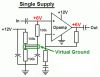
(figure 7 at the bottom of the doccument)

What they are trying to do is create a phantom ground for the op amp. Unfortunately I have no electrical engineering degree, only years of fooling around with electronics, so I am a bit uneducated.

I will be using the op amp to power a fet and I assume I will still use the output of the op amp directly into the base of the fet, however I do not understand why the output is grounded.

Also, how is it that there are grounds within this circuit if there is no ground? (hence one battery source) are these ground points different from other ones I may have from the input circuit? Are they just common connection points within this circuit?

Bassically I want to know how to use this effectively, I will have three stages in my circuit, an input, this op amp, and a fet. I want it all off of the same power source.

Thanks for takin a look.
 
I think it is an error. It looks like a voltage follower to me and the output should not go to ground. The output voltage should be Vs/2 with the values shown.
 
that would make alot more sense, I mean I dont know alot, but from what I do know, I would think that grounding the output would complete the circuit, making it useless for the mosfet stage.
 
WAIT! maybe there is an error and maybe not I found another schematic...

https://www.analog.com/library/analogDialogue/archives/35-02/avoiding/Fig1.gif

Here they have a resistor between the output and the ground, effectively creating a voltage drop / potential across it. This make sense to me to some degree, but how would I connect the mosfet stage to this, the only applications where I have seen something like this is where you connect aboce and below the resistor, but only one output goes to the mosfet..... so would you ground the emmiter of the mosfet and then connect the gate above the resistor?
 
No professional, but I think you are thinking of the resistor load wrong, you dont connect above or below it for the mosfets, the whole mosfet stage IS the resistor. But i dont knwo what bw1 or bw2 etc. are. maybe someone else can fill in those holes.
 
The kid who drew that extremely confusing figure 7 schematic has the battery backwards. He is crazy to ground the positive supply and the output of the opamp. He has grounds all over the place.

Figure 7 is supposed to be a virtual ground circuit that is a very low impedance at half the supply voltage for biasing other opamps.

BW1 is a highpass filter in the negative feedback loop of the opamp.
BW2 is a lowpass filter at the input of the opamp.
The BW1 and BW2 are reversed in the two circuits. Very confusing.
 
wow, always makes learning a blast and a half....well scrap that then, what about this setup for using a battery and an op amp..

**broken link removed**

will this be a suitable circuit for driving a high power mosfet of a single supply?
 
The virtual ground opamp is for biasing other opamps, not for driving a Mosfet.
 
do you know of any websites that might have a schematic on how I would go about driving a power mosfet with a single power supply? I would like this to be able to be run on a marine set up, so only one lead acid battery is availible (could do two, but I would like it to be portable and transferable to other boats.)
 
Armagdn03 said:
do you know of any websites that might have a schematic on how I would go about driving a power mosfet with a single power supply? I would like this to be able to be run on a marine set up, so only one lead acid battery is availible (could do two, but I would like it to be portable and transferable to other boats.)

What they are trying to do is create a phantom ground for the op amp. Unfortunately I have no electrical engineering degree, only years of fooling around with electronics, so I am a bit uneducated.

The diagram shows a OPA being used to create a phantom ground, thats why the output of the OPA is grounded. By using this phantom ground in your system as the common ground reference, it effectively splits the single supply voltage into two, ie +V/2 and -V/2.
So if you had a single supply source of say, 12V, then with reference to the phantom ground [the grounded output of the OPA] you will have a +6V and a -6V for your other OPA's in the system.


I will be using the op amp to power a fet and I assume I will still use the output of the op amp directly into the base of the fet, however I do not understand why the output is grounded.
Yes the final output of your 'other' amplifier can drive a FET, BUT you must consider the output of the 'other' OPA may swing +/-V, so it will determine how your FET is connected.

Also, how is it that there are grounds within this circuit if there is no ground? (hence one battery source) are these ground points different from other ones I may have from the input circuit? Are they just common connection points within this circuit?

Its a STAR ground, ALL the grounds shown are taken to a Common point, which is the phantom ground.

Bassically I want to know how to use this effectively, I will have three stages in my circuit, an input, this op amp, and a fet. I want it all off of the same power source.

Post a diagram of your planned circuit and we will advise.
 
hi,
This diagram may help to make it clear.
 
Last edited:
That makes tons more sense! thank you so much for your help, Ill see what I can do for a diagram, and hopefully I can create something useful! thanks
 
Clear as mud.
You don't need a virtual ground opamp when you want a Mosfet to drive a load. You also probably don't need any opamp.

Just let the signal (logic level from a PIC?) drive the Mosfet and use a logic level Mosfet.

The circuit with the virtual ground opamp has the load current flowing through the output of the virtual ground opamp and the current is probably way too high for the output of the opamp.
 
audioguru said:
Clear as mud.
You don't need a virtual ground opamp when you want a Mosfet to drive a load. You also probably don't need any opamp.

Just let the signal (logic level from a PIC?) drive the Mosfet and use a logic level Mosfet.

The circuit with the virtual ground opamp has the load current flowing through the output of the virtual ground opamp and the current is probably way too high for the output of the opamp.

Hi audioguru,
While I always value your opinion, on this occasion I am puzzled why you cannot understand my explanatory diagram
for the phantom ground the OP keeps asking about.

I DONT anywhere in my post, say he should use a Phantom OR do I say he should use an OPA to drive a FET,
I am attempting to answer his question.[ he understands the diagram]

Please read my posts carefully, as I do yours, comment and criticism are always welcome, BUT don't keep missing the 'can'

Regards.
 
ericgibbs said:
Hi audioguru,
While I always value your opinion, on this occasion I am puzzled why you cannot understand my explanatory diagram
for the phantom ground the OP keeps asking about.
I have made hundreds of battery-powered single supply circuits with opamps and have never used a virtual ground opamp circuit.
Opamps have an extremely high input impedance. Just a voltage divider with a bypass capacitor is needed to bias an opamp at half the supply voltage.

An old LM358 or LM324 can be used without a virtual ground because their inputs work at the negative supply voltage and the output is pulled to the negative supply voltage by the load.
 

Attachments

  • virtual ground.PNG
    virtual ground.PNG
    9 KB · Views: 701
audioguru said:
I have made hundreds of battery-powered single supply circuits with opamps and have never used a virtual ground opamp circuit.
Opamps have an extremely high input impedance. Just a voltage divider with a bypass capacitor is needed to bias an opamp at half the supply voltage.

An old LM358 or LM324 can be used without a virtual ground because their inputs work at the negative supply voltage and the output is pulled to the negative supply voltage by the load.

hi,
I too have never had cause to use a phantom ground in the many hundreds of OPA' I have designed and manufactured.
Knowing their shortcomings I avoid using them.
A lot of the circuits you keep referring to, are AC coupled amplifiers, a simple voltage divider and bypass maybe
good enough for AC, but what do you do for low level DC OPA's that need their outputs to swing +/-???

I expect you do the same as I do, use a dual power supply.

So I say again, please comment and criticise on what I have posted.
 
problem is that the load can be up to 90+ amps (for short durations) can a logic level mosfet handle this sort of a load? I was under the impression that you needed an entermediary stage, hence driving the mosfet with a large op amp.
 
Status
Not open for further replies.

New Articles From Microcontroller Tips

Back
Top