Continue to Site

Welcome to our site!

Electro Tech is an online community (with over 170,000 members) who enjoy talking about and building electronic circuits, projects and gadgets. To participate you need to register. Registration is free. Click here to register now.

  • Welcome to our site! Electro Tech is an online community (with over 170,000 members) who enjoy talking about and building electronic circuits, projects and gadgets. To participate you need to register. Registration is free. Click here to register now.

dc motor control

Status
Not open for further replies.

aamir1

Member
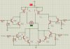
Hi guyz howz all??? i want to control a dc motors speed and direction im using H bridge circuit for that based on B.J.T transistors. But im confused at one point the motors specifications show that its rated current in 500mA but as i change the speed with PWM the current will also change through the motor and i want to design a H bridge for that so what current should i choose for Ic saturation as i am confused that if the current will change through the motor the transistors will leave saturation and go into active mode and dissipiate more power and heat what is the solution for this please help me
 
hi aamir1,

In a correctly designed H-bridge the transistors should always be in saturation mode or off.

The PWM drive signal to the H-bridge should be of a sufficient amplitude as to ensure that the bridge transistors are operated in saturation mode or off.

Varying the Pulse Width will vary the average current thru the motor so its speed will vary.

E
 
A DC motor draws maximum current when it is stalled. When it starts running it is stalled and its current will be maximum.
Design the H-bridge so that the transistors can saturate at the maximum motor current.
 
but when the current from the motor decreases the transistors will run out of saturation as if i design for maximum current let say 5A and the motor starting current is 5A and then it decreases to 2A then the transistors will run out of saturation how should i control this?
 
but when the current from the motor decreases the transistors will run out of saturation as if i design for maximum current let say 5A and the motor starting current is 5A and then it decreases to 2A then the transistors will run out of saturation how should i control this?

hi,
Not really,

What we are saying is the Base drive current must be high enough to drive the transistors into saturation at the Maximum current, this means at lower currents the transistors will still be saturated .
 
hi guyz ive attached the following circuit of h bridge designed by me using B.J.T`s plz comment about the circuit whether it is correct or not and also tell me which analogy is better to use should i use mosfet and a driver i.c or this circuit is better plz comment about this thanx a lot
 

Attachments

  • h bridge.jpg
    h bridge.jpg
    233.2 KB · Views: 202
I think this needs some modifications, first you will need diodes for protection check out L298 motor driver ic for more infomation regarding this
 
ya ive attached diodes also in proteus i didnt use them but in practical i will use 6A diodes but is it better to use B.J.T or mosfet circuit ???
 
if you use mosfet then you can use high curent motors without problem. But you may need to adjust input voltage to the mosfets gate to on fully. Normal power mosfet can handle more than 20 A , eg. IRF540. Transistors at that current are huge and you may need to input higher current than mosfet since mosfets are voltage driven.
 
Last edited:
waht is the exact condition to saturate a n channel mosfet is it this that When VGS > Vth and VDS ≥ ( VGS – Vth ) or is it necessary to use boot strapping I.C ir2110 ???
 
waht is the exact condition to saturate a n channel mosfet is it this that When VGS > Vth and VDS ≥ ( VGS – Vth ) or is it necessary to use boot strapping I.C ir2110 ???
Vth for a Mosfet is when it is almost turned off with a current of only 0.25mA. The datasheet for every Mosfet shows its very low on-resistance when its gate-source voltage is 10V for most Mosfets.

Your upper Mosfet is probably a source-follower so its gate voltage must be 10V higher than its drain voltage when it turns on. The boosted voltage is provided by bootstrapping.
 
Status
Not open for further replies.

Latest threads

New Articles From Microcontroller Tips

Back
Top