Continue to Site

Welcome to our site!

Electro Tech is an online community (with over 170,000 members) who enjoy talking about and building electronic circuits, projects and gadgets. To participate you need to register. Registration is free. Click here to register now.

  • Welcome to our site! Electro Tech is an online community (with over 170,000 members) who enjoy talking about and building electronic circuits, projects and gadgets. To participate you need to register. Registration is free. Click here to register now.

DC Motor and H-Bridge Problem

Status
Not open for further replies.

Molimo

New Member
Ok here goes, am trying to build an H-Bridge (2 actually) for a small robot for a class project. I am using 2 TIP125 and 2 TIP121 as Darlington Gates, now here is the main problem. When i try to drive a motor with a load (gearbox) the H-bridge just crashes my Microcontroller (meaning it resets it) and if I try it with the motor on its own it works perfectly.

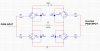
Here is how it is Wired. I have the Tip125 on top row, 3Volt VCC coming from a source going to the Emitter of the Transistors. Base goes to a 1K resistor then to the PWM from the Microcontroller and then the Collector pin goes to the next transistor which is a TIP121. His base goes to a Resistor (1K) then to the same PWM. and its Emitter goes to the ground.

Now that would be ONE side since the other side I insert a Inverted PWM (compared to the other one).

Now like I said it works perfectly when I use a motor without load, it seems that when I try using a Gearbox motor that the Startup current is too high and tries pulling it from the MCU for some reason. I just dont get why my MCU Resets (the wheels turn for half a second) and then I have to power down the MCU and power it back up.

Also the Stall Current of the Motor is 2A, i've never seen it reach there but it normally needs around 700 mA to Start the motor then it will run fine for a Current of 300-400mA. This was tested by plugging the motor directly to the Source.

Thanks for the Advanced Help

Any thoughts will be appreciated

Marc
 

Attachments

  • Schematic.jpg
    Schematic.jpg
    134.5 KB · Views: 481
it may caused by the drop of power or EMI of the motor. There are 2 way to solve the problem. first the power must be capable of handling more peak current. A big capacitor (say 1000uf) with low internal resistance must be placed as close as possible to the emitters of Q3 and Q4. the second way is to isolate digital and analog power supply. This could be approch by a inductor (ferrite bead) and proper design of grounding.
 
So with the capacitor would I be putting it from my VCC directly to the Ground? which would be the closest to the Transistors Q3 and Q4? and for the Inductor, where would it be placed?, if you could make a small design on paper that would help alot.

If not its still ok, Ill look into those two things.

Also just a thought, Could I use a ULN2803A, from the Microcontroler to the 4 Gates? That would raise the Current allowed to the H-Bridge without drawing too much from the MCU

Thanks Again

Marc
 
it's not because of the H bridge drops too much current from the MCU. it's because of it drops too much peak current from the power supply. the capacator should be placed at the nearest place to the emmiter pins of Q3 and Q4, connected between VCC and GND. This will offer the power supply much higher peak current capability .
 
Hello,

What else happens sometimes with circuits that have a control circuit
plus a driver section is that the driver section turns on and draws a
huge current which pulls the power supply voltage down to a much
lower level and that resets the control circuit because the control
circuit looses its power for a short time.
The solution there is to isolate the control circuit power supply with
a resistor or inductor and add additional filtering capacitance
across the control circuit power input to ground. This allows the
control circuit to work normally even if the drive power is pulled
down temporarily.
The way many circuits like this are powered is like this...
The power to the bridge is unregulated, and the power to the
control circuit is regulated and extra filtered. This adds a bit
of isolation by itself.

What else could be happening is that you are seeing the effect of
turning on both one upper and one lower on the same side of the
bridge which causes a huge current to flow (much more than load
current) and that pulls the whole power supply line down too,
and also causes a high level EMI to radiate out of the power
circuit and into the control circuit. The best way to avoid this
problem is not to add more capacitance, but to either introduce
some dead time or else add a little more dead time to what is
already being used. A circuit like this with no dead time is not
a good idea anyway, even when the whole thing appears to work
ok.
 
Last edited:
It is common practice to use separate supplies for digits and motors when possible. At the very least run the motor directly from the supply and line regulate the MCU.
The caps may help smooth out very brief sags, but I suspect your supply is underated for the application.
 
Ok here's what I have analysed so far. The capacitor does not do anything more to my circuit. so with it it still doesn't work but I will keep it there since it doesn't hurt.

I am using two different sources from the university, one is outputing 9V to a LM7805 (5 Volt regulator) which goes to the Microcontroler. And that source is rated for 1A of current, which is well enough for the MCU since it only takes about 30 mA when running.

For the H-Bridge part, I am using a Source of 4.4V (Outputs exactly 3V to the motor) and this Source is rated for 2A, which is the Stall current of my motors and i've never seen them taking more than 700mA.

So both sources are seperate and both grounds are connected together.

When I try to run with the PWMs from the motor, the MCU will reset on its own( I know because on startup it goes in a Stop Loop which waits for me to press a button before I can send a signal and After I try to run it it goes back to that loop).

Now i tried puting out VCC to one side of the bridge and Ground to the other side. well that worked PERFECTLY.

So to sum up, the problem relies on that MCU, My h-bridge is supposely demanding too much current from the MCU and it crashes. I have 1K resisitors with a voltage of 5V to the gates. so that means the h-Bridge shoul only demand a maximum of 20mA and the MCU can handle over 100mA.

Any more Ideas?

Thanks

Marc
 
Yes.

How are the grounds connected? Is it possible that the current in the ground
wire is influencing the voltage drop in the MCU ground wire? This is a common
problem. The idea to solve it is to run the ground from the big power supply
right to the transistor emitters, then the ground from the small supply right
to the negative terminal of the MCU chip, with cap nearby. Then, connect
the ground from the MCU to the emitter of the transistors with another wire
perhaps through a 10 ohm resistor to isolate the grounds.
That's three ground wires:
One from big power supply to emitters
One from little power supply to MCU
One from MCU to emitters (possibly with 10 ohm in series).

See if any of that helps.
 
Have you tried running the MCU as stand alone? That is to say verify the MCU works without driving the H-bridge.
 
Yes, it actually works perfectly when I run the motor outside of the gearbox, because it doesn't demand a high current it works really good. but as soon as I use the gearbox, I need more current to start the motor and then it won't work at all.

And for the grounds, they're all connectect together.

Thanks

Marc
 
Your bridge may be drawing 'shoot-through' current. When your MCU output is passing through about 2.2V (half of your 4.4V supply), both the top and bottom Darlingtons are turned on.

A resistor from base to emitter on each transistor should reduce this effect. I would begin with 2k2 (2.2k). If it helps but there's still a minor problem then try 1k8. If it totally eliminates the problem but the motors run slow then see if you can get away with with 3k3.
 
Status
Not open for further replies.

New Articles From Microcontroller Tips

Back
Top