Continue to Site

Welcome to our site!

Electro Tech is an online community (with over 170,000 members) who enjoy talking about and building electronic circuits, projects and gadgets. To participate you need to register. Registration is free. Click here to register now.

  • Welcome to our site! Electro Tech is an online community (with over 170,000 members) who enjoy talking about and building electronic circuits, projects and gadgets. To participate you need to register. Registration is free. Click here to register now.

DC Boost Converter Problems

Status
Not open for further replies.

vne147

Member
Hello everyone. I'm working on a project and have run into to some trouble. I'm hoping someone here can help me resolve it.

I'm building a prototype of a small, battery powered, motion sensor. I've made the PCB and have started soldering components onto it. I've gotten as far as the power supply portion of the circuit but it's not working correctly.

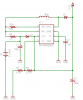
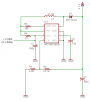
The power supply is a DC-DC boost converter based on the MC34063EDB IC. I'm powering it with 3V and need about 5.7V at the output. I've attached a schematic showing the portion of the circuit I've built so far and also, here is a datasheet for the MC34063EDB.

Ultimately, I want to power the circuit from 2 AAA batteries but when I tried that, it didn't output 5.7V; it output closer to 28V. After seeing this, I supplied the board with 3V from my bench power supply just to see what would happen and when I did, the circuit seemed to work fine. I measured 5.68V at the output.

Next, with the circuit still powered from my bench power supply I measured the current being drawn by the circuit and was surprised to see about 285 mA. I didn't look at it through an oscilloscope and my multimeter is not of the best quality so I'm not sure how close to reality the number is but it still seems surprisingly high to me. I mean there isn't even a load hooked up to it yet.

What I think is happening is when the circuit is hooked up to the AAA batteries, it is drawing more current than they can supply. As a result, their combined voltage drops to around 1.5V (which I've measured) and that undervolts the IC. The IC stops working, the battery voltage rebounds, the IC turns on again, the battery voltage drops, and so on. I think this astable operation is causing the higher than intended output voltage. Conversely, when I power the circuit from my bench supply, it has no problem giving 285 mA at 3V and the IC works normally.

So my question is this; why is the circuit drawing that much current? Shouldn't it be much much less especially since there is no load connected to the output yet? 285 mA seems like a ridiculously high quiescent current consumption. What can I do to reduce the current? Can I use a larger inductor? A different diode? Does anyone have any ideas?

Thanks in advance for your help.

mc34063edb-circuit-png.58916
 

Attachments

  • MC34063EDB Circuit.PNG
    MC34063EDB Circuit.PNG
    24 KB · Views: 5,009
If you feedback is broken you will get very high voltage out (28v) and too much current draw. Check R1, R2 and the connection Pin-5. Pin-5 should be 1.2 volts. R2 might be open or too large. R1 could be too low. Pin-5 could be open.
 
If you feedback is broken you will get very high voltage out (28v) and too much current draw. Check R1, R2 and the connection Pin-5. Pin-5 should be 1.2 volts. R2 might be open or too large. R1 could be too low. Pin-5 could be open.

Ron,

Thanks for your reply. I verified all the connections before posting this thread and they appear to be fine. Besides, if there was a problem with the pin 5, R1, or R2, I'd expect the circuit to exhibit the same unintended behavior regardless of whether it was powered by the AAA batteries or my bench power supply. However, it works fine when powered with 3V from by bench supply. It only doesn't work when powered by the 2 AAA batteries. Ideas?
 
Hi,

Inductor looks kinda smallesh, 150uH better at those lower frequencies, but the main problem is that the ic chip is not made to work at under 3v. Not sure where you got the idea it should work with two AA batteries, or did you mean three? Two AA's will load down right away to under 3v and even if not it wont take long anyway.
Zetex makes converter chips that work well under 3v, but im sure other companies do too.

Edit: wow you want to work with two AAA cells? That's not going to work very well with this chip. Try three instead.
 
Last edited:
Mr Al,

Thanks for the reply. I'll try a larger inductor. I have a few 180 µH inductors that take up roughly the same footprint. As far as the other point you made no, I did not mean to say 3 AAA batteries. I understand the datasheet says the IC is designed to work between 3-40V but I have had success in the past at getting it to work at a lower voltage. I've tested it down to 2.4V before the output became unstable. Not sure what detrimental effect this might have but it worked in a few past applications for me. I was hoping it would work here too. The only thing I changed between this build and past builds was the inductor size. At any rate your Zetex suggestion is intriguing. Can you recommend a part number?
 
Hi again,

What do you have to power with this circuit, how much output current?

You got this chip to work with less than 3v in the past? What is different about this circuit then, are you powering it differently or something, or did you decide to try a lower value inductor? I think this chip frequency is around 30kHz so 50uH might be too small. 100uH or 150uH should do it unless you need a nice smooth output then you might need a higher value. Depends what you have to run with this thing.

For this project, the circuit will have a peak demand of about 80 mA.

I have gotten this chip to work in the past on 2 AA batteries. This is my first attempt at using AAA batteries. Some time ago just to see how low I could go, I hooked a similar MC34063 circuit up to my bench power supply and monitored the converter's output while varying the bench power supply voltage. I was able to get the bench power supply down to 2.4V before the converter's output started going wonky. I don't remember how much load was on the circuit when I did this test. The only thing I changed between this build and prior ones was the inductor size. In the past I have used 180µH inductors. This time I'm using a 47 µH one.
 
I just got home and swapped out the 47µH inductor for a 180µH one and it works! At least it works so far without it supplying any load. I'll start soldering in the rest of the circuit now and see what happens. When I first switch it on there is some in rush current which I think is slightly undervolting the batteries. The output voltage starts at around 20V but within a second, everything stabilizes and I get a nice steady 5.68V. Not ideal I know but this project is only a proof of concept prototype so it should work well enough for that purpose. Do you think I could place an inductor between the positive terminal of the battery and the circuit's input to limit the in rush? For the next project using similar power sources and voltage levels, I'm going to try one of those Zetex chip as an alternative. Thanks for the help!
 
Hi,


You're welcome. Nice to hear you got it up and running too. I'm a little surprised that it works down that low, but have to say i wouldnt be able to recommend this practice to anyone because it already violates one of the data sheet specs. You might try heating and cooling the chip and see if it remains working down to 2.4v or doesnt.

So you need a regulated output voltage then? 80ma isnt too much current really so something has got to work :)

When you put an inductor in series with the battery you can limit inrush current but may introduce high spikes during startup because the inductor will see a switch as output and so the inductor will become connected, then disconnected, then connected again, then disconnected again, etc. What could work a little better is an inductor and well chosen capacitor across the input of the chip.
But before i do that i think i would check the inrush with the 150uH or higher inductor, and possibly even make that larger if you can. A larger inductor should lower inrush too.
The startup sometimes takes a while to get into regulation so the inductor current might overshoot. It's a question of inductor size and other circuit timings. If the timings are fast relative to the inductor size, the current doesnt have time to overshoot by much, so the bigger the inductor the less inrush current in most cases. This also means a smoother output voltage.
Also a smaller cap means it starts faster so less inductor current overshoot, but of course it's not always possible to lower the output cap value unless the inductor value is increased.

Zetex ZXSC400 chip comes to mind, but we'd want voltage regulation instead of current regulation.
Zetex ZXLD1615 has regulated output, input down to 2.5v.
 
Last edited:
I just got home and swapped out the 47µH inductor for a 180µH one and it works! At least it works so far without it supplying any load. I'll start soldering in the rest of the circuit now and see what happens. When I first switch it on there is some in rush current which I think is slightly undervolting the batteries. The output voltage starts at around 20V but within a second, everything stabilizes and I get a nice steady 5.68V. Not ideal I know but this project is only a proof of concept prototype so it should work well enough for that purpose. Do you think I could place an inductor between the positive terminal of the battery and the circuit's input to limit the in rush? For the next project using similar power sources and voltage levels, I'm going to try one of those Zetex chip as an alternative. Thanks for the help!
Boost converters are notorious for drawing high peak currents: a typical solution is to put a large value (low ESR) switching capacitor near the VCC pin of the IC so it can draw peak current from the cap and not the source. 100uF is not enough, try as much as will fit and make SURE it is a low ESR switcher cap (aluminum or tantalum).
 
Last edited:
Hi,


You're welcome. Nice to hear you got it up and running too. I'm a little surprised that it works down that low, but have to say i wouldnt be able to recommend this practice to anyone because it already violates one of the data sheet specs. You might try heating and cooling the chip and see if it remains working down to 2.4v or doesnt.

So you need a regulated output voltage then? 80ma isnt too much current really so something has got to work :)

When you put an inductor in series with the battery you can limit inrush current but may introduce high spikes during startup because the inductor will see a switch as output and so the inductor will become connected, then disconnected, then connected again, then disconnected again, etc. What could work a little better is an inductor and well chosen capacitor across the input of the chip.
But before i do that i think i would check the inrush with the 150uH or higher inductor, and possibly even make that larger if you can. A larger inductor should lower inrush too.
The startup sometimes takes a while to get into regulation so the inductor current might overshoot. It's a question of inductor size and other circuit timings. If the timings are fast relative to the inductor size, the current doesnt have time to overshoot by much, so the bigger the inductor the less inrush current in most cases. This also means a smoother output voltage.
Also a smaller cap means it starts faster so less inductor current overshoot, but of course it's not always possible to lower the output cap value unless the inductor value is increased.

Zetex ZXSC400 chip comes to mind, but we'd want voltage regulation instead of current regulation.
Zetex ZXLD1615 has regulated output, input down to 2.5v.

Mr Al,

Thanks for the detailed explanation. Unfortunately, I don't have any larger value inductors than 180µH so I'm stuck with that one for now. I also kind of cornered myself with the footprint it's supposed to fit into so even if I were to order a higher value inductor, I would probably have trouble finding one small enough. But all that might be a moot point anyway because it appears I've taken two steps forward and one step back.

Last night while I was still basking in the glow of my success, I decided to verify that the circuit would still work while supplying a load. I connected a 47Ω resistor across the output and ground to draw roughly 120 mA. When I did that, the output voltage took a nose dive to around 3.2V and the whole circuit started making this lovely whining noise. I guess that means the switching frequency slowed down enough to enter the range of human hearing. So, it appears I'm not out of the woods yet.

All this is especially frustrating to me because I usually test everything before I etch the PCB. In this case I tested most of the circuit but skipped the power supply portion because I've had repeated success with this design in the past and I wrongly assumed that the few changes I was making were minor, and shouldn't have adversely affected the circuit's performance. Silly me...

In an effort to avoid simply starting over, I have one final idea I'm going to try before resorting to drastic changes. Yesterday while I was reading a Zetex data sheet for the ZXLD1321, I noticed that it has a feature where it can operate in boot strap mode and I started wondering if couldn't do the same thing with my circuit. The data sheet says that the MC34063 will start up with as little as 1.2V so as long as the battery voltage doesn't drop below that, the converter should start up and as soon as the output voltage rises above the battery voltage the output should start supplying the IC. I attached a scematic of how I think this might work. Can anyone see any reason why it wouldn't?

I guess I could also just byte the bullet and use some AAA Li-ion batteries that have a nominal voltage of 3.6V. If I go that route I'd remove the MC34063 from the circuit and just supply my two LDO regulators directly from the batteries. I have a 3.3V and 5V regulator in the circuit with a maximum drop out voltage of around 400 mA at my current consumption.

Thoughts?

Boost converters are notorious for drawing high peak currents: a typical solution is to put a large value (low ESR) switching capacitor near the VCC pin of the IC so it can draw peak current from the cap and not the source. 100uF is not enough, try as much as will fit and make SURE it is a low ESR switcher cap (aluminum or tantalum).

Hi Bountyhunter, thanks for the reply. For this to help reduce the peak startup current, wouldn't the cap have to be connected to the batteries all the time? Even with the power switch off?

mc34063-bootstrapped-png.58945
 

Attachments

  • MC34063 Bootstrapped.PNG
    MC34063 Bootstrapped.PNG
    16.5 KB · Views: 3,866
The 34063 is not a good choice for a boost converter running from 3v input, it has a drop of over 1.5v in the output drivers, (and probably more than 1.5v at 280mA!) so it is struggling to do anything well at 3v input.

How much current do you need at 5.7v and what will it be powering? Maybe we could suggest a better circuit?

Hey Mr RB.

I need about 80 mA at 5.7V. I'm powering an 18F1320 PIC, an SCA61T inclinometer IC, 2 LEDs, and an Xbee 1 mW transceiver. I've been reading through a few of the Zetex datasheets since Mr Al suggested them and they seem much more suited for my application than the 34063. I guess I just got comfortable with using this IC and tried to get too much out of it. If I have to go back to the drawing board and make another PCB I will but I'm trying to salvage what I've done do far.

Today I ran across some 3.6V Li-ion AAA batteries. I could use those, bypass the boost converter altogether and just supply my 2 LDOs directly. An ugly solution I know but it should save me some work.

Do you have any thoughts on the boot strapping idea? I have a couple DIP 34063s. If I have time tonight I'll test it out. It may just be another case of me trying to get too much out of the little guy.

What do you think?
 
Hi,

Do you have the spec's for your new inductor? We could take a look and see if that is causing any problems. Low ESR in the inductor is more important for boost converters than for other types because the series resistance gets nearly multiplied by the output/input voltage ratio or more.
With an ESR too high the converter might not start, or exhibit very low efficiency or not even be able to output the full required voltage level.
 
Last edited:
1. If you need slightly less than 5v, you can always use a capacitor voltage-doubler.

2. The actual number of turns on the inductor is important. You can also put inductors in series, just like resistors, to see the effect.

3. The fact that the initial voltage is above 6v is a danger-point.

4. The type of AA cell is also important.
 
Last edited:
The high value inductor is likely working because of its extra wire resistance. It also limits the coil charge current for given drive frequency. Too much inductance for given chop frequency may prevent you from getting maximum output current needed.

With a 0.22 ohm current limiting resistor you will draw 1.4 amps peak during startup which, along with 47 uh inductor saturation, is likely causing the battery voltage collapse. Your peak running coil current necessary for 80 mA at 5.7 vdc output with 3vdc input will be about 500 mA so you should be able to raise the 0.22 ohm up to about 0.47 ohms which will limit the startup surge to 650 mA peak. This may help you get through the startup surge without too much current draw from battery.

If you saturate the coil during startup it makes the input current surge shoot up. The saturate current rating for the 47 uH inductor is 480 mA which is usually spec'd at point where inductance drops to 80% (38 uH) of original low current value. With a 0.22 ohm current limit resistor you are banging the coil into pretty deep saturation at startup surge.
 
Last edited:
Thanks everyone for your input. I haven't tried the boot strapping idea yet but I should have time to do that tomorrow. If you never hear from me again it's because it didn't work and I blew myself up.

Hi,

Do you have the spec's for your new inductor? We could take a look and see if that is causing any problems. Low ESR in the inductor is more important for boost converters than for other types because the series resistance gets nearly multiplied by the output/input voltage ratio or more.
With an ESR too high the converter might not start, or exhibit very low efficiency or not even be able to output the full required voltage level.

This is the 180µH inductor that I switched to.

SDR0805LTEB181K

It claims to have a resistance of .77Ω but I have no idea if that's considered low or not.

1. If you need slightly less than 5v, you can always use a capacitor voltage-doubler.

2. The actual number of turns on the inductor is important. You can also put inductors in series, just like resistors, to see the effect.

3. The fact that the initial voltage is above 6v is a danger-point.

4. The type of AA cell is also important.

Can you elaborate on point 3 above?

Also, what type of cells would you recommend. I am using normal alkaline AAAs from Duracell at the moment.

The high value inductor is likely working because of its extra wire resistance. It also limits the coil charge current for given drive frequency. Too much inductance for given chop frequency may prevent you from getting maximum output current needed.

With a 0.22 ohm current limiting resistor you will draw 1.4 amps peak during startup which, along with 47 uh inductor saturation, is likely causing the battery voltage collapse. Your peak running coil current necessary for 80 mA at 5.7 vdc output with 3vdc input will be about 500 mA so you should be able to raise the 0.22 ohm up to about 0.47 ohms which will limit the startup surge to 650 mA peak. This may help you get through the startup surge without too much current draw from battery.

If you saturate the coil during startup it makes the input current surge shoot up. The saturate current rating for the 47 uH inductor is 480 mA which is usually spec'd at point where inductance drops to 80% (38 uH) of original low current value. With a 0.22 ohm current limit resistor you are banging the coil into pretty deep saturation at startup surge.

I changed the inductor to a 180µH one (part number above). Also, I was under the impression the .22Ω resistor was for current sensing by the IC. Do you think it's OK to change it to .47Ω?
 
3. The fact that the initial voltage is above 6v is a danger-point.

You said The output voltage starts at around 20V but within a second, everything stabilizes and I get a nice steady 5.68V
The circuit can "lock-up" when the voltage of the supply drops and this can either drain the cells completely or produce very high output voltages.

Your best choice is to use a 3.6v cell It has twice the energy-density of AAA cells and comes in rechargeable. Or even 3 x AAA cells
 
Status
Not open for further replies.

Latest threads

Back
Top