Electro Tech is an online community (with over 170,000 members) who enjoy talking about and building electronic circuits, projects and gadgets. To participate you need to register. Registration is free. Click here to register now.
Welcome to our site! Electro Tech is an online community (with over 170,000 members) who enjoy talking about and building electronic circuits, projects and gadgets. To participate you need to register. Registration is free. Click here to register now.
I can't find the answer to this anywhere.
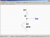
Data sheets for many darlingtons show a diode across the collector and emitter. What does it do?
I've heard of "speed up diodes", where are they in the darlington, and what do they do?
The one collector to emitter is a clamp diode to protect the transistor from inductive "kick".
The speed up is from the input to the base of the 2nd transistor. It makes it turn off quicker.
The output diode does not arrest the positive-going inductive voltage spike when the darlington turns off.
A clamp diode is supposed to be connected across the inductive load, not across the driving transistor.
It has a built in diode across C and E. This is the body diode, right? Is it there as a byproduct of how a darlington is manufactured (like a MOSFET's is) or is it intentionally made as part of the circuit? I don't think it does anything useful, but I'm not sure.
That drawing shows a commutation diode that would be placed across an inductive load to kill the back emf spike.
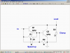
Look at this darlington:
http://www.datasheetcatalog.org/datasheet/motorola/MJ10012.pdf
It has a built in diode across C and E. This is the body diode, right? Is it there as a byproduct of how a darlington is manufactured (like a MOSFET's is) or is it intentionally made as part of the circuit? I don't think it does anything useful, but I'm not sure.
The C-E diode is used in place of the diode that is normally connected across the inductive load. It allows current to decay in the inductor very rapidly, but still damps ringing and prevents damage to the transistor. The transistor must be a high voltage device (most have breakdown rated at several hundred volts). Some also have the base-emitter speedup diode incorporated.
I always wondered what a very high voltage darlington is used for. It survives the high flyback voltage from an inductive load. So the parallel diode clamps ringing.
This site uses cookies to help personalise content, tailor your experience and to keep you logged in if you register.
By continuing to use this site, you are consenting to our use of cookies.