Electro Tech is an online community (with over 170,000 members) who enjoy talking about and building electronic circuits, projects and gadgets. To participate you need to register. Registration is free. Click here to register now.
Welcome to our site! Electro Tech is an online community (with over 170,000 members) who enjoy talking about and building electronic circuits, projects and gadgets. To participate you need to register. Registration is free. Click here to register now.
I use two Ni-Mh battery. So my power supply is 2.4V. The load is a 2V led. What do you advise for this voltage limit ? what kind of circuit correct for this supply ?
If the max allowed current for the 2.0V LED is 30mA then Ohm's Law says that a current-limiting resistor of 13.33333 ohms will cause it. I don't know what is the max allowed current for your LEDs.
You must limit the current to an LED, not the voltage. One million volts will light an LED for a very long time if the current is limited to its current rating or less.
The two Ni-MH cells will have a voltage of 2.8V when they are fresh from the charger.
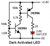
thank you for this information but i just want to make a circuit which is dark activated ldr circuit for one led with only two battery. also the activation must be precise.
Connect a resistor 220k from 2N3904 base to 2N3906 collector. That will add positive feedback. The LED should be on or off but not dim. Try different values of resistor.
The collector voltage of the PNP is always much higher than the voltage at the base of the NPN. Therefore there won't be any positive feedback, the LED will just be turned on all the time.
It might work if you carefully make a voltage divider to reduce the 2V to 2.3V at the collector of the PNP down to about 0.55V to 0.65v at the base of the NPN.
This site uses cookies to help personalise content, tailor your experience and to keep you logged in if you register.
By continuing to use this site, you are consenting to our use of cookies.