Continue to Site

Welcome to our site!

Electro Tech is an online community (with over 170,000 members) who enjoy talking about and building electronic circuits, projects and gadgets. To participate you need to register. Registration is free. Click here to register now.

  • Welcome to our site! Electro Tech is an online community (with over 170,000 members) who enjoy talking about and building electronic circuits, projects and gadgets. To participate you need to register. Registration is free. Click here to register now.

Custom PIC circuit support / project

Status
Not open for further replies.

smudgepost

New Member
Hi, I was building a small LED timer project with a 555 timer (within my scope) then extra features were added that put the job outside my scope. A PIC option might be better, though this is beyond my expertise and wondered if anyone would be able to provide the skills as a little home-work. I need help with the circuit as I have to make about 40..

A bit about the project:

It is a circuit for a toy, with a flashing LED and digital beep or pip sound to match the blinking. I'd like to have the flash with and without sound/switchable. It needs to be as compact as possible so probably limited to button batteries and 1.5 - 3V.

It also needs to include a super bright LED or flash bulb and reed switch. The concept is that when the circuit is broken, the LED flash speeds up, as does the beep, then the super bright flashes, a little like a time bomb effect from an X-Files or something.

Specifics:

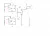
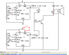
Timer circuit pulsed flash of LED, like typical 555 circuits, delay about 2 seconds, pulsed not on/off blink.
Switch for on with sound, on without sound and off.
Pieze speaker or similar outputting digital 'bip' coinciding with led flash, similar to ecg machine.

High power possibility
 
Last edited:
I'm a little confused by your post. You say that the added features makes the project outside of your scope, so you decided to use a PIC instead. But apparently, the PIC is also outside of your scope since you're asking for other to provide a solution. IMO, the PIC is complete overkill for this project. You're better off putting your efforts towards making an electronic solution, especially considering your limited power.

Also, having high-power features are contradictory to your requirement for a small and limited power device. Engineering isn't like an "all you can eat" buffet. You have to make compromises.
 
Actually, I think a 12F5XX will do all that quite simply and probably with fewer parts and lower overall cost.

If you define more exactly what you want, someone here could provide the code for you. Can you read assembly? Do you have the PIC programmer?

John
 
Hire a builder..

Hi, thanks for your replies. I think I need help to design the circuit diagram for sure. Although on a budget I would certainly look to pay for help. I offered to make a toy and use a simple 555 timer LED setup for the effect as it looks the part and there are simply hundreds of schematics online, but the features have grown through the 'buzz' of the whole ordeal and I simply don't know enough about electronics (yet.. and time is against me) to build it.

I would happily provide specifics if I know what a circuit designer would need to know. For me, compact is key, but the rest is open to ideas. I only have a parallax stamp but can probably rig the board to my PC to upload code onto a suitable PIC, or if the simpler electronics option is preferred, can copy the design from a breadboard to a small stripboard.
 
Last edited:
this schematic should work??

you need to compute how fast you want the leds to flash
**broken link removed**
use a 556 instead of the two 555's.
the output transistor may be overkill as it is a darlington transistor.
this should get you started hopfully.
suggested timming componets
for 2 seconds = R1-100k, R2-200k, C1-10uf
for faster 90k, 10k, 10uf
entire circuit should fit on a 1x1 inch board maybe.
 

Attachments

  • led toy.PNG
    led toy.PNG
    20.8 KB · Views: 352
I am extremely grateful for this, thank you very much. I will be building this on my breadboard today.

Some of the components I can't quite make out, such as which is the R1 and R2 and did you use two standard LEDs for the effects or two different types (until I assemble it I can't guess what will happen to the one mounted by the TIP120).

For ease I will probably use this setup not a 556. What size diode would you suggest for pin 3 on the second timer?

Many, many thanks.
 
this might help you along

you need to calculate the value of R5 which is determined by current draw of high pwr led and the beeper and 555 output.
switch in red is to activate second timer to speed up blinking and beeping
this should work but no guarantees
breadboard and test first.
inserted a 2n2222 in place of darling ton for simplicity figuring not everyone has a darling ton in their parts box.
remember keep R5 high enough as the 555 has max of 200ma but I like to keep below 100ma if possible.why max out your parts?
good luck
 

Attachments

  • toy.PNG
    toy.PNG
    34 KB · Views: 388
Status
Not open for further replies.

Latest threads

New Articles From Microcontroller Tips

Back
Top