AtomSoft
Well-Known Member
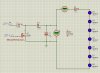
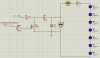
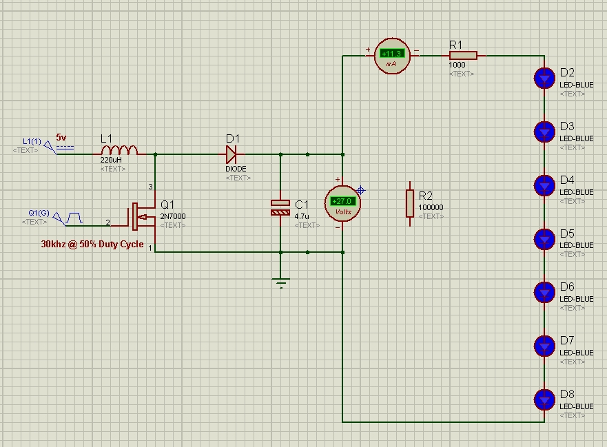
Hey guys me again  Im trying to make my own boost circuit to save some money heh.. I want to know about this i came up with... Im trying to power 7 white LEDs from 3.7 to 5v....
I wanted to know ... since i made this there is about a 80% chance somethings bad or will go bad heh... take a look at the schematic and tell me if it has a chance of working...
Im trying to make my own boost circuit to save some money heh.. I want to know about this i came up with... Im trying to power 7 white LEDs from 3.7 to 5v....I wanted to know ... since i made this there is about a 80% chance somethings bad or will go bad heh... take a look at the schematic and tell me if it has a chance of working...