Continue to Site

Welcome to our site!

Electro Tech is an online community (with over 170,000 members) who enjoy talking about and building electronic circuits, projects and gadgets. To participate you need to register. Registration is free. Click here to register now.

  • Welcome to our site! Electro Tech is an online community (with over 170,000 members) who enjoy talking about and building electronic circuits, projects and gadgets. To participate you need to register. Registration is free. Click here to register now.

Current through diode.

Status
Not open for further replies.
Don't forget you need RMS current to know the heating effect. I think SCR manuals publish RMS vs. conduction angle graphs.

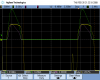
Here is a scope capture of the diode dissipation in the power supply I mentioned a few posts ago.

There was a 5 amp load on the supply.

The yellow trace is the voltage across the diode, the green trace is the current through the diode and the purplish trace is the math function showing the instantaneous product of the diode voltage and current.

At the bottom of the screen can be seen the average of the diode current, the RMS value of the diode current, the average diode dissipation and the duty cycle of the diode voltage.

The peak diode current is just about 20 amps, and the peak forward voltage just touches 1 volt.

These diodes would probably be ok, but there isn't any heat sinking. The manufacturer recommends a copper foil area of .8" by .8" for each lead. This power supply has essentially no foil. The diode leads are soldered into small pads which go off to the rest of the circuitry. The manufacturer also says to only have .375" lead length; this design has about 1" leads.

The RMS current doesn't really tell the whole story as to dissipation because the voltage across the diode is somewhat constant. If one were to use the RMS current to derive dissipation by use of the I^2*R formula, what would you use for R?

If the diode current isn't too outrageously high, as in this case, then it's better to use the average voltage across the diode (about .9 volts by inspection) times the average current (2.549 amps here) getting about 2.3 watts, which is quite close to the 2.32 watts calculated by the scope.
 

Attachments

  • eBaySupply.png
    eBaySupply.png
    34.5 KB · Views: 132
Have a look at the second page of the GE spec sheet I posted.

It's not enough to know the average current through the diode. You must take account of the conduction angle. If the diode current is a narrow pulse, then the heating of the diode can be much larger than you would think just from the average current.

To further expand on this point. Sometimes the forward voltage versus current that you see in a spec sheet fails to be exponential at really high currents. I've seen some curves that become quite straight at high currents. This is because the resistance of the diode is becoming dominant. When this happens, the dissipation in the diode becomes nearly proportional to the RMS value of the current. But, at the lower currents, where the Vf-If curve is exponential, the voltage across the diode is nearly constant for most of the conduction period, and the dissipation is more nearly proportional to the average current.

And, of course, the behavior switches over as the current goes from the low current regime to the high current regime.

Actually, the dissipation is a combination of these effects, with one or the other being dominant, depending on the forward current.

If the dissipation is measured (or calculated) by averaging the product of the instantaneous forward voltage and current, then the correct result will be obtained regardless of whether the low or high current regime dominates.
 
Status
Not open for further replies.

Latest threads

New Articles From Microcontroller Tips

Back
Top