GagoX
New Member
Hello everyone, ")
I would like to share my ideas about the project I am working in right know...may be you have cool ideas too!
I am trying to design a circuit as simple as possible that allows me to control the current that flows through a LED array but at high frequencies (for communication purposes).
for example, using a DC voltage with a sinusoidal voltage source of 1 Vpp in series, a resistor of 10 ohms and one white LED (everything in series) I can drive the current up to 20 Mhz (measuring the voltage in the resistor) (-3db cut off frequency) (basically the speed at which blue light can follow).
Because one LED has a voltage drop of 3.5V typically when I set the DC voltage to 4.5 and a signal of 1Vpp , I get a modulation depth between 100mA and 0mA. (Although white LEDs are rated to work with 20mA, for pulsed operation the stand 100mA)...at least that's what I calculated.
In reality LEDs are non-linear elements, thus increasing the current to 100mA, will increse the voltage drop to 4 volts may be...and therefore with 4.5 volts DC supply I have a very distorted signal...so I can go up a little bit and try..and error, and try, and error, etc.
Of course my problem is that the current depends on the voltage drop of the diode. So I start looking at circuit alternatives.
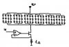
I am pretty sure you know this circuit...signal comes to the positive pin of a OPA, the the output of the OPA goes in the base of a transistor, which its collector is attached to the cathode of the LED (or anothe...how was it?..never remember the names), the othe pin of the LED to supply voltage, the emitter is conected to a resistor and also to the negative pin of the OPA...a nice controled current source.
now my problems come:
Imagine that I have 10 of this LEDs in paralell...or in some other series/paralell configuration. I would loove to modulate 100mA passing to every one of them...or in other words..modulate 1A..(actually 1A x 3.5 V =3.5W)
(ina series configuration would be less current but more voltage=the same power)
now...CAN I DO THAT?...whith the controlled current source, can I modulate 1 A at 20 Mhz??? Can you think of more options to drive high currents at high frquencies...
Know that I am writing...I think...may be one current source per LED and then conect every positive terminal from the OPA together...(not very elegant ;-)
but then the question is a normal DC source capable to able to give that current at high frequencies??? (I have acces to a very big, modern, cool looking DC source with 0-5V/5A,0-25V/1A in the lab)
Actually the best would be to drive a LED Array of 12, 4 lines in parallel of 3 LEDs in series, whith 166mA. And even better 6 of these matrices in parallel, to have an modulating current of 1A.
I search in google and I didn't find nothing. (May be I should look in the books of electronics?..but I don't have any!
Any help would be very appreciated.
Chau
I would like to share my ideas about the project I am working in right know...may be you have cool ideas too!
I am trying to design a circuit as simple as possible that allows me to control the current that flows through a LED array but at high frequencies (for communication purposes).
for example, using a DC voltage with a sinusoidal voltage source of 1 Vpp in series, a resistor of 10 ohms and one white LED (everything in series) I can drive the current up to 20 Mhz (measuring the voltage in the resistor) (-3db cut off frequency) (basically the speed at which blue light can follow).
Because one LED has a voltage drop of 3.5V typically when I set the DC voltage to 4.5 and a signal of 1Vpp , I get a modulation depth between 100mA and 0mA. (Although white LEDs are rated to work with 20mA, for pulsed operation the stand 100mA)...at least that's what I calculated.
In reality LEDs are non-linear elements, thus increasing the current to 100mA, will increse the voltage drop to 4 volts may be...and therefore with 4.5 volts DC supply I have a very distorted signal...so I can go up a little bit and try..and error, and try, and error, etc.
Of course my problem is that the current depends on the voltage drop of the diode. So I start looking at circuit alternatives.
I am pretty sure you know this circuit...signal comes to the positive pin of a OPA, the the output of the OPA goes in the base of a transistor, which its collector is attached to the cathode of the LED (or anothe...how was it?..never remember the names), the othe pin of the LED to supply voltage, the emitter is conected to a resistor and also to the negative pin of the OPA...a nice controled current source.
now my problems come:
Imagine that I have 10 of this LEDs in paralell...or in some other series/paralell configuration. I would loove to modulate 100mA passing to every one of them...or in other words..modulate 1A..(actually 1A x 3.5 V =3.5W)
(ina series configuration would be less current but more voltage=the same power)
now...CAN I DO THAT?...whith the controlled current source, can I modulate 1 A at 20 Mhz??? Can you think of more options to drive high currents at high frquencies...
Know that I am writing...I think...may be one current source per LED and then conect every positive terminal from the OPA together...(not very elegant ;-)
but then the question is a normal DC source capable to able to give that current at high frequencies??? (I have acces to a very big, modern, cool looking DC source with 0-5V/5A,0-25V/1A in the lab)
Actually the best would be to drive a LED Array of 12, 4 lines in parallel of 3 LEDs in series, whith 166mA. And even better 6 of these matrices in parallel, to have an modulating current of 1A.
I search in google and I didn't find nothing. (May be I should look in the books of electronics?..but I don't have any!
Any help would be very appreciated.
Chau