Tupinambis
New Member
Greetings,
I am working on my first analog design project which is to build a two-wire current loop interface (preferably 4-20ma) for transmitting the output of an instrumentation amplifier measuring the voltage across a solenoid. An important feature of the project is that the two wires transmit the appropriate interface current and also provide power to the instrumentation circuit and necessary voltage reference. The final design will be used for high temperature applications and that is why I wish to design my own instead of using a commercially available IC.
So far, my setup is the following:
A 2 op-amp (single supply) instrumentation amplifier with referenced
inputs, who's output is represented by V_SIG
A 5V reference used to provide the in-amp reference
A voltage controlled current source driven by V_SIG
I was hoping to use op-amps with low operating currents such that the idle
current (V_SIG = 0V) is lower than 4ma, the additional ~16mA would be
drawn by the VCCS. For testing purposes I have been using a signal
generator to simulate the in-amp output but the rest of the circuit is
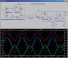
shown below.
Recently, I added the load resistor (used for measuring the interface
current) as shown in the schematic but found that it drastically
attenuated my AC amplitude (1kHz) which was previously 8mA, while the DC level
remained at 12mA. What could explain this behavior?
RESPONSE: Attenuation was due to large bypass capacitance, effectively working with the load resistor as a LPF.
Any additional comments or recommendations are much appreciated since I am
not sure if this is the best approach for designing my interface.

I am working on my first analog design project which is to build a two-wire current loop interface (preferably 4-20ma) for transmitting the output of an instrumentation amplifier measuring the voltage across a solenoid. An important feature of the project is that the two wires transmit the appropriate interface current and also provide power to the instrumentation circuit and necessary voltage reference. The final design will be used for high temperature applications and that is why I wish to design my own instead of using a commercially available IC.
So far, my setup is the following:
A 2 op-amp (single supply) instrumentation amplifier with referenced
inputs, who's output is represented by V_SIG
A 5V reference used to provide the in-amp reference
A voltage controlled current source driven by V_SIG
I was hoping to use op-amps with low operating currents such that the idle
current (V_SIG = 0V) is lower than 4ma, the additional ~16mA would be
drawn by the VCCS. For testing purposes I have been using a signal
generator to simulate the in-amp output but the rest of the circuit is
shown below.
Recently, I added the load resistor (used for measuring the interface
current) as shown in the schematic but found that it drastically
attenuated my AC amplitude (1kHz) which was previously 8mA, while the DC level
remained at 12mA. What could explain this behavior?
RESPONSE: Attenuation was due to large bypass capacitance, effectively working with the load resistor as a LPF.
Any additional comments or recommendations are much appreciated since I am
not sure if this is the best approach for designing my interface.
Last edited: