Hi,
I've been thinking about this circuit for a while now and I need some help.
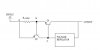
I am trying to achieve current limiting and perhaps a short circuit protection (I don't want to use a fuse) using the attached circuit.
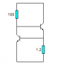
The voltage regulator is LM350 and it will be used to regulate voltages from 30 V to 1.2 V. However, I would like to force the LM350 to conduct a current of 1A max in the worst case. I would like the output current to be 3A max (I am aware that LM350 can handle 3A but I would still like to limit it.).
1. How can I achieve current sharing between Q1 and the voltage regulator, if Q2 is placed in the circuit as shown? Before I decided to use a current limiter circuit, I used a small resistor instead of Q2, and the ratio of that small resistor and R_sense determined current sharing. Can something similar be done here?
2. When voltage drop accross R_sense reaches 0.7V, Q2 will turn ON and current from Q1 will be shunted through Q2. How can I prevent this current from exceding 1A through the regulator? I don't want to insert a large series resistance between Node C and regulator, because my output voltage will drop.
3. Also, I was thinking about adding a larger resistor (100 ohms) between the base of Q2 and emitter of Q1 to protect Q2 from damage during normal operating conditions of the pass transistor. Will this large resistor affect the turn-ON voltage of Q2?
I understand the npn-current limiting technique, but when I think of using a pnp pass transistor I can't seem to design the circuit.
Thanks for the help!
p
I've been thinking about this circuit for a while now and I need some help.
I am trying to achieve current limiting and perhaps a short circuit protection (I don't want to use a fuse) using the attached circuit.
The voltage regulator is LM350 and it will be used to regulate voltages from 30 V to 1.2 V. However, I would like to force the LM350 to conduct a current of 1A max in the worst case. I would like the output current to be 3A max (I am aware that LM350 can handle 3A but I would still like to limit it.).
1. How can I achieve current sharing between Q1 and the voltage regulator, if Q2 is placed in the circuit as shown? Before I decided to use a current limiter circuit, I used a small resistor instead of Q2, and the ratio of that small resistor and R_sense determined current sharing. Can something similar be done here?
2. When voltage drop accross R_sense reaches 0.7V, Q2 will turn ON and current from Q1 will be shunted through Q2. How can I prevent this current from exceding 1A through the regulator? I don't want to insert a large series resistance between Node C and regulator, because my output voltage will drop.
3. Also, I was thinking about adding a larger resistor (100 ohms) between the base of Q2 and emitter of Q1 to protect Q2 from damage during normal operating conditions of the pass transistor. Will this large resistor affect the turn-ON voltage of Q2?
I understand the npn-current limiting technique, but when I think of using a pnp pass transistor I can't seem to design the circuit.
Thanks for the help!
p