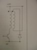
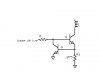
It is a project of Switched Reluctance Motor whereby I need to use some winding connections to build up winding current quickly and allow rapid collapse of winding current when the transistor is turned off. This is the controller to make the switched reluctance motor spins. However, the peak transistor current in this case cannot exceed 8A or the objective of this project will fail. Together with this question, I attach it with the winding connections. Thanks a lot......
Continue to Site