I googled for a constant current source and came along the lm317.
I both simulated it (in multisim) and built up the simple circuit, but I neither get a constant current when i attach a load!
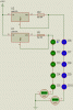
I followed this circuit: https://www.roboternetz.de/bilder/konstantlm317.gif.
Everything is fine if the circuit remains open, however attaching a load let the current drop significantly.
Do you see any failures in "my" design?
Thanks
I both simulated it (in multisim) and built up the simple circuit, but I neither get a constant current when i attach a load!
I followed this circuit: https://www.roboternetz.de/bilder/konstantlm317.gif.
Everything is fine if the circuit remains open, however attaching a load let the current drop significantly.
Do you see any failures in "my" design?
Thanks