Electro Tech is an online community (with over 170,000 members) who enjoy talking about and building electronic circuits, projects and gadgets. To participate you need to register. Registration is free. Click here to register now.
Welcome to our site! Electro Tech is an online community (with over 170,000 members) who enjoy talking about and building electronic circuits, projects and gadgets. To participate you need to register. Registration is free. Click here to register now.
hello every one.
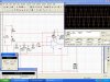
I have designed an Oscillator using 741 op-amp. it can supply 20mA maximum But i have to have 3A for my circuit purpose. so please suggest me the current Amplifier that i can design to have 3A at the output.
hello every one.
I have designed an Oscillator using 741 op-amp. it can supply 20mA maximum But i have to have 3A for my circuit purpose. so please suggest me the current Amplifier that i can design to have 3A at the output.
hi,
I would ask the same as Bychon, looks like an 'ac' motor drive.??
If the answer is yes, then you will most likely need a push/pull FET drive.
The resistive split 12V supply will give you problems at 2.4A if you try to reference the FETs to the virtual 0V.
hi,
At that voltage and current any transistor being driven by a sine wave input and producing a sinewave output will have to be highly rated and mounted on a heatsink.
Look at this complementary transistor pair pdf for an example.
What you are trying to do is not easy, is it essential that the motor is powered by a sine wave rather than a 300Hz square wave.??
@ Eric
yes it is written on the motor that i requires these things to run in a fine mood.
and what about this Transistor? can i just simply bias it like we bias the normal common emitter Amplifier to give me 3A?
@ Eric
yes it is written on the motor that i requires these things to run in a fine mood.
and what about this Transistor? can i just simply bias it like we bias the normal common emitter Amplifier to give me 3A?
hi,
With these transistors you will require another transistor to drive them.
If you look at the datasheet you will see the HFE is about 10 at the collector current you require.
So for a collector current of 2.4A, a base drive current of at least 2.4/10 [ 0.24A] is required.
A driver transistor for each power transistor would require a 0.5A collector rating.
You could consider using N and P MOSFET's in place of the the power transistors.
Most AC motors will work well with a square wave drive, a square wave power driver would be easier to design and also be more efficient.
@hero
yeah! i am not aware of the drives if available in market. and i am designing it for educational purpose. i wanna learn and also want to know about available drives.
yeah! you are absolutely right. i only have a truck battery of full size (i don't know what we would name it ).
what i was think is that, that first i'll convert D.c into A.c with 300Hz and then amplify the current and then after having enough current i'll step-up the voltages.
What do you suggest? is it possible?
If yes, this would mean a step up to about 165Vrms [240Vpk] using a 300Hz switching inverter, with a centre tapped winding in order to give 240Vppk.
Even at 100% efficiency for a 2.4Arms motor current thats at least 24Vamp draw from the battery.
If the 'η' of the inverter was say, 70% thats approx 35A.
I would suggest you post a more detailed drawing of how you see the project connected to the motor.
No. it's a 12v battery.
I am attaching the block diagram, what i was thinking that i would design my circuit in this manner. but you people are saying that this is not very efficient so i'll change my idea according to yours.
This site uses cookies to help personalise content, tailor your experience and to keep you logged in if you register.
By continuing to use this site, you are consenting to our use of cookies.

") ).
).