Hello Everybody,
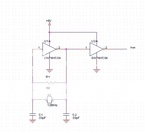
I build this crystal oscillator circuit like the diagram below. When I use IC HD74HC04 of Hitachi Semiconductor or 74HC04 of NXP semiconductor (formerly Philips semiconductor). It works well. But when I use SN74HC04 of Texas Instruments. It does not work ! Could anyone give me any suggestion ? Thanks.
I build this crystal oscillator circuit like the diagram below. When I use IC HD74HC04 of Hitachi Semiconductor or 74HC04 of NXP semiconductor (formerly Philips semiconductor). It works well. But when I use SN74HC04 of Texas Instruments. It does not work ! Could anyone give me any suggestion ? Thanks.
