EarlOfWessex
New Member
Hello, first post for me. I've looked everywhere, and have found nothing.
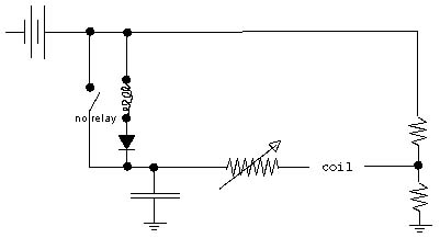
Ok, so the theory goes...
the relay is closed, charges the capacitor, and removes the potential across the relay, opening it.
the capacitor discharges at a speed controlled by the pot, until its low enough to trigger the relay, the process is repeated.
the coil would see a sawtooth wave, with both positive and negative swing (because of the resistor to ground), with the speed controlled by the pot.
I know that any relay would burnout quickly, and for even low frequency waves I would need to use something else.
but would this work in theory?
the goal of this is to produce a variable horizontal sweep for an oscilloscope.
I have ripped apart an old CRT monitor, because I can't afford a real scope .
.
I know the wave slope wont be straight, but I don't think it will matter, as long as its consistent.
Thanks for taking the time to read this.
Ok, so the theory goes...
the relay is closed, charges the capacitor, and removes the potential across the relay, opening it.
the capacitor discharges at a speed controlled by the pot, until its low enough to trigger the relay, the process is repeated.
the coil would see a sawtooth wave, with both positive and negative swing (because of the resistor to ground), with the speed controlled by the pot.
I know that any relay would burnout quickly, and for even low frequency waves I would need to use something else.
but would this work in theory?
the goal of this is to produce a variable horizontal sweep for an oscilloscope.
I have ripped apart an old CRT monitor, because I can't afford a real scope
.I know the wave slope wont be straight, but I don't think it will matter, as long as its consistent.
Thanks for taking the time to read this.