Gday folks!
I was looking for some help on the net and came accross this forum, and am now a new member. Anyways, I'm studying engineering at uni and we have a project where we must build a preamplifier (balanced) to add high sensitivity ranges to a CRO. The input impedence must be >1k and must be able to drive a 100 Ohm load.
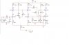
My plan is to cascade a 'cascode differential pair' (ie balanced input), with 20 dB gain, with a simple transistor combination to make up the final 20 dB (100 V/V is the requirement).
Now, I have the cascode pair running well, ie required bandwidth and gain, but I've run into trouble with my second stage. I've tried using a simple common emitter, but i can't seem to get it to give me 10V/V, even after applying the appropriate formula's.
I was wondering if there were any suggestions as to what type of second stage amp to use, whether a feedback pair or even something simpler. I wish to use only npn type transistors, preferrably BC548's as they supposedly work up to 300MHz (my required bandwidth is 40Hz to 15MHz).
Some assistance would be greatly appreciated
 Nick D
I was looking for some help on the net and came accross this forum, and am now a new member. Anyways, I'm studying engineering at uni and we have a project where we must build a preamplifier (balanced) to add high sensitivity ranges to a CRO. The input impedence must be >1k and must be able to drive a 100 Ohm load.
My plan is to cascade a 'cascode differential pair' (ie balanced input), with 20 dB gain, with a simple transistor combination to make up the final 20 dB (100 V/V is the requirement).
Now, I have the cascode pair running well, ie required bandwidth and gain, but I've run into trouble with my second stage. I've tried using a simple common emitter, but i can't seem to get it to give me 10V/V, even after applying the appropriate formula's.
I was wondering if there were any suggestions as to what type of second stage amp to use, whether a feedback pair or even something simpler. I wish to use only npn type transistors, preferrably BC548's as they supposedly work up to 300MHz (my required bandwidth is 40Hz to 15MHz).
Some assistance would be greatly appreciated
Nick D