Continue to Site

Welcome to our site!

Electro Tech is an online community (with over 170,000 members) who enjoy talking about and building electronic circuits, projects and gadgets. To participate you need to register. Registration is free. Click here to register now.

  • Welcome to our site! Electro Tech is an online community (with over 170,000 members) who enjoy talking about and building electronic circuits, projects and gadgets. To participate you need to register. Registration is free. Click here to register now.

Counter help

Status
Not open for further replies.

EfeVural

New Member
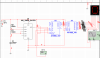
I want to create a clock in multisim i created the circuit attached.. It counts from 0 to 9.
Fine but i want to

1- Make it 0 to 5 for the parts of 60 minutes and 60 seconds.

2- And also i want to synchronize each 7segment. One think i thought to sychronize is to give voltage to reset input of 4510. When i connect and run it 7seg gives 0, when i turn it to ground it doesnot start from 0.

3- One last thing where should i measure the frequency? If i directly measure it from the output of 555 timer, i dont get 1khz (i think in order that each digit should be flashed one second later) while i get an okey timing in the 7 segment when i compare it with my own watch... In order to get accurate timing i should find out where i have to measure 1khz...
 

Attachments

  • counter.png
    counter.png
    41.2 KB · Views: 1,161
In practice, you will be lucky if a 555 keeps time better than +-2%, which is nowhere near good enough for a "clock". You should start with a 32768 Hz watch crystal divided by 2^15 (15 bits of a 16bit binary counter to create accurate 1 second ticks.

There are many ways to make a divide by 6 counter whose bits count in BCD sequence. Which counter IC do you want to use?
 
doesnot matter i am just trying to build up stuff for hobby. So as i understand counting 012345 is up to the counter model right? I mean, i cannot do this with the ones i used in my attachment?

also i measure the time measured by ossiloscope to pass one digit(from analyzing 7 segment inputs) = like 20ms.. when i start the circuit it is like my own watch 1 seconds(of course by error) each digit?
 
Have you downloaded and read the data sheet? Those inputs are the "preset" inputs. If used, you can preset the counter to any value 0-9, and it will count-up from there. The Co is "CarryOut" used for cascading multiple counters. Its all on the data sheet.
 
1- Make it 0 to 5 for the parts of 60 minutes and 60 seconds.

2- And also i want to synchronize each 7segment.
..

i didnt get both of the above points, in your diagram only one 7 segment is there, but you told for 60sec & 6o min can you explain a bit more?
syncronize each segment with what?
if you want to make it only 0-5 then you have to give a reset pulse when 4510 reads 0110. you have to use some gates to get the reset. same way you can configure for manual reset by a push button switch to reset to 0 at any time.

Edit: if you want to repeat the seme configuration for many digits, then the reset input for one 4510 would be the clock for the next one & so on.
 
Last edited:
resetting gave me an idea i connected an and gate to the digital codes coming to the decoder when both b and c gives 1 (digit 6) it resets. I mean of sychronizing as i attached. In my attachment for example there are two 7 segments which will count upto 59. I used reset also for sychronizing the first "Zero"s(00)(in order not the mix two resetting ideas i used or gate) i connected a key to reset both oh the 7segments when i open the key the circuit starts from 00... In order to synchronize two 7segments i tried to change square wave frequency of the 555 squarewave generator of the 0to5 7segment... But when simulating ; in 0-5 7segment doesnot always change from 0 to 1 when the 0-9 7segment completes its cycle. So there is some sychronization problem... maybe i should try quarts cristals
 
there existed another problem everythying works fine there is sychronization between segments. But when i open the key(resetting key) while the first 7segment runs properly the others instantly jumps from 0 to 1. There is no problem with the other cycles(first segment continues its first 0-9 cycle and the second 7 segment becomes 2; when the second 7segment completes its 0-5 cycle the third segment becomes 2etc..).. But i could not understand why the immediate increase in 2nd and 3rd segments occurs?

by the way i thank you very much for whom commented on my post....
 

Attachments

  • counter4.png
    counter4.png
    24.7 KB · Views: 343
i setup everything as in the datasheet (carryouts to carry in : cascading 4510s and all clock inputs from the same frequency square wave generator in paralel) and the problem disappeared. Everything is fine now. Only need is to use more accurate oscillator i think..
 
finally you are done, thats great. for clock, 555 is not a good idea when accuracy is needed. you have to have a crystal oscillator at high frequency and then divide it using some counters to get 1 Hz. search for 1Hz time base on this forum or on net, you may get many.,
 
hello again i could not continue my work for a while for some reason.. anyway there is a problem: as i said i use an and gate to reset the counter when it comes to 6(i take the inputs from binary code of 6: 0110) it is okey it does the job. However; when i connect the 3rd 7segment which is 0-9minutes part: it does not become 1 when seconds pass 59 and become 00 again.. If i dont use and gate then the seconds go to 99 and after that minutes becomes 1 and seconds 00 :gives 100; so no problem... however whlie using and gate i used an ossciloscope and there was neither drop nor rise(always + some voltage steady) in the voltage of the carry out of second counter which goes to the carry in of the 3rd counter(which should trigger the 3rd counter to work properly). And there is no problem when i do not use and gate in 2nd counter and it counts from 00 to 99; which means voltage of the carryout of the second counter is allways positiv escept drops to 0 at 9 and rises again at 0 which sends the triggering to the 3rd counter...

So how can i owercome this problem? I searched the forum and found related problems. There were some solutions suggested with preset inputs; however as i understood, the function of the presets is that they decide the beginning number of the count. However i try to fix the ending number of the count to 5(after that come 0. So i could not relate my problem to those solutions...
 
you have connected the carry out put of the 2nd to the 3rd segment clock, instead you have to take out put from AND (0110) to clock the 3rd segment.
ie: when 2nd segment get a reset, the same signal will be the clock for the 3rd segment.
 
Hello,

That fix may work depending on the clock requirement of the counter, but if it proves to be unreliable (clock pulse too narrow) then you can take the carry output directly from the bit 3 of the previous counter, or else the inverted bit 3 of the previous counter. This will provide a nice clock signal for the next counter.

Note that the reason it doesnt work with the normal carry output is because the counter internal 4th stage Flip Flop never gets changed (ie the count never gets above 6 so it never reaches at least 8 which would be required to generate a normal carry output).
 
Status
Not open for further replies.

Latest threads

New Articles From Microcontroller Tips

Back
Top