Electroenthusiast
Active Member
This Post is the continuation of https://www.electro-tech-online.com/threads/room-person-counter-help.97193/ ...
**broken link removed**
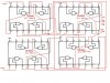
I actually will be using IR LED's n Detectors, using the detectors i will have to UP/DOWN count the counter(Probably IC-7495) based on the direction of the person entering/leaving.
How to do it?
**broken link removed**
I actually will be using IR LED's n Detectors, using the detectors i will have to UP/DOWN count the counter(Probably IC-7495) based on the direction of the person entering/leaving.
How to do it?
Last edited: