Hi guys, thisi s my first post here, and I´m happy I found this site, the circuit I´m trying to make is the following:
**broken link removed**
Basically I have to preactivate the calculator so everytime you press the "=" key you get 1+1 and counts evrey object that blocks the light in the LDR.
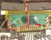
My doubt is that how do I connect the calculator to the relay, I opened up the calculator and this is what I can see:
**broken link removed**
The red spot I marked is the "=" key, since I'm new in to electronics I really don´t have a clue how to connect the calculator to the spot I marked, also I would be really thankful if someone could explain me how the transistors are useful in this circuit (I really don´t know) and if what is the purpose of the component "VR1", since I simulated this circuit with a basic software "livewire", and when I increased or decreased it´s value it didn´t change anything.
**broken link removed**
Also here is the link where I found this project and a video.
Link
https://www.youtube.com/watch?feature=player_embedded&v=YsEGomCY9eQ
**broken link removed**
Thanks in advance for any help on the matter.
**broken link removed**
Basically I have to preactivate the calculator so everytime you press the "=" key you get 1+1 and counts evrey object that blocks the light in the LDR.
My doubt is that how do I connect the calculator to the relay, I opened up the calculator and this is what I can see:
**broken link removed**
The red spot I marked is the "=" key, since I'm new in to electronics I really don´t have a clue how to connect the calculator to the spot I marked, also I would be really thankful if someone could explain me how the transistors are useful in this circuit (I really don´t know) and if what is the purpose of the component "VR1", since I simulated this circuit with a basic software "livewire", and when I increased or decreased it´s value it didn´t change anything.
**broken link removed**
Also here is the link where I found this project and a video.
Link
https://www.youtube.com/watch?feature=player_embedded&v=YsEGomCY9eQ
**broken link removed**
Thanks in advance for any help on the matter.