Continue to Site

Welcome to our site!

Electro Tech is an online community (with over 170,000 members) who enjoy talking about and building electronic circuits, projects and gadgets. To participate you need to register. Registration is free. Click here to register now.

  • Welcome to our site! Electro Tech is an online community (with over 170,000 members) who enjoy talking about and building electronic circuits, projects and gadgets. To participate you need to register. Registration is free. Click here to register now.

Could use assistance on a timer project

Status
Not open for further replies.

warlc

Member
I'm working on a timer to interface with a clock and music box movement.
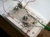
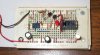
It will be used to sense the clock (electronic in this case) chime, then pulse a timer to control a relay (1 sec) . The relay will turn on the music box movement, play one chorus of song and mechanically turn off . I'm sensing the clock chime an opto sensor connected through a mosfet. The mosfet will turn on the 555 timer. I have breadborded the attached circuit (with a led in place of the relay and a switch to represent the opto switch). It works, but I'm getting on 1.5 volts between led and ground.
can anyone help?
 

Attachments

  • clktimer.pdf
    9.8 KB · Views: 315
Should be more like 1.7V, that's the LED forward voltage. In that circuit, the LED will hold the voltage to the relay at only 1.7V. If you remove it, the voltage will go up - but it will still have that resistor on the collector of the 2N2222 in series with the relay, and it may not pull in.
 
thanks for the reply. i took out the led and put a meter across the 2222 to ground. i get .97 volts to .1 volts (is that a cap discharging? i checked my connections then took a reading from the mosfet discharge to ground. i don't get any reading now. replaced the mosfet.. still no reading. i'm attaching a photo of breadboard.
 

Attachments

  • PICT0182.JPG
    PICT0182.JPG
    42.5 KB · Views: 166
Your circuit is a mess:
1) The Mosfet's source is not connected so it won't work. It needs 10V on its gate to conduct anyway and your circuit gives its gate only about 5V.
Why did you use an expensive 450V Mosfet?
2) Your 555 and transistor do not have a power supply so they will never work.
3) The 1k resistor that is the collector load of the transistor will not turn on the relay.
 
You are a steely-eyed rocket man, audioguru. I mentioned the one about the collector resistor, but missed that wretched mess with the MOSFET and blatant lack of a supply for the 555 circuit.

In addition to the floating source (or incorrectly connected drain and missing supply voltage) AND the dismal 20ma of on-state current it could conduct with Vgs = 5V, it will still never work because it's an N-channel device trying to work as a source-follower off a very inadequate voltage. You either need to get a different N-channel mosfet and connect it from ground up, or use a P-channel mosfet there and pull its gate low.
 
timer problem

thanks for responding. yes it is a mess, that's because i'm an electrical person and not an electronics person. i'm cutting and pasteing from a mosfet circuit and a 555 timer circuit and my electrical logic is not electronic logic. i was trying to drive the 555 ic from the drain of the mosfet. i selected the mosfet based on a gate threshhold 2v min and 4v max and the smallest amp rating. most of the 555 circuits i've seen used 12v supplies. all i really know right now is that i need a "non-contact" sensing of the clock and a relay to control my mechanical actuator and i have 6volts supply. i looked at hall effect sensor and i'm going to try an opto sensor but they are not "on" or "off" (like a limit switch)so i need a device to sense the max or min voltage coming from the sensor and turn on the relay for a short pulse then off. i can do the rest mechanically (using a timer motor) if necessary. I thought i could use the mosfet to do this but it isn't working out. how can i do this?
 
The opto may be able to do it for you without the mosfet.

Pin 4 on the 555 is reset, it needs to be held within .7V of ground to do its thing. Connect a 100k resistor on the opto's collector, other end to +6V. Connect the opto's emitter to ground. Measure the voltage on the collector. You don't mention the number on the opto, but it should hold that voltage to less than .7V. Interrupt the opto. The voltage should go near 6V.

Got that so far? Next step is to disconnect the 555 Reset line from Vcc and connect it to the opto collector and resistor point you just measured. Now when the beam is broken, the voltage will go up on the reset line and the 555 will operate.
 
Last edited:
The gate threshold voltage of a Mosfet is when it begins to conduct only 0.25mA so it is nowhere near fully turned on.
 
clock timer help

thanks duffy,
i will try that when the i get the optos. attached an updated schematic. is that right? i have a question. when the clock strikes the hour and the flag trips, it takes a while for the flag to move (as the clock hand moves off the hour). i believe that the 555 is set for an astable operation. would this tend to start the timing cycle again?
 

Attachments

  • clktimer.pdf
    9.3 KB · Views: 196
The 555 is an astable oscillator that keeps repeating.
But the relay won't work. It should be connected from the collector of the transistor to the positive supply voltage.
 
clock timer help

hi thanks,
the transistor is inverting the signal from the 555. the 555 times for 24 sec
on power up then pulses the relay for 1 sec.
 
The transistor shorts the relay, it doesn't drive the relay. Nothing drives the relay.
 
i changed the shematic to correct connection between the transistor and the relay. I breadboarded it and when connecting pin 4 on 555 to vcc nothing happens with the timer.
 

Attachments

  • clktimer.pdf
    8.9 KB · Views: 163
Need more to go on than that. Measure some voltages.
 
Those are good for a start - from that, your transistor should be on. It's off. Why?

1. It's burned out
2. You have it hooked up wrong.

Is it getting hot?

3. The relay diode is backwards
4. The relay current is too high

Short out the collector and emitter with a piece of wire. Does the relay snap on?
 
Looks like you have the drive circuit completely upside-down. The emitter's on Vcc, relay on ground.
 
Last edited:
The transistor has a base current of 4.3mA so it should be able to drive a 144 ohm relay coil.
Maybe you have the collector and emitter pins of the transistor connected backwards?

Do you have a high current ordinary 555 or a low current Cmos one?

How many ohms or what is the current of the relay's coil?
 
the relay coil is 115 ohms. i had a cmos 555 but replaced it with an ordinary
(i don't know how to test them) way back when this one was working. the relay works when i put a jumper across collector and emitter. i replaced the 470k pot with a 10k resistor to shorten delay.
 
Status
Not open for further replies.

Latest threads

New Articles From Microcontroller Tips

Back
Top