Continue to Site

Welcome to our site!

Electro Tech is an online community (with over 170,000 members) who enjoy talking about and building electronic circuits, projects and gadgets. To participate you need to register. Registration is free. Click here to register now.

  • Welcome to our site! Electro Tech is an online community (with over 170,000 members) who enjoy talking about and building electronic circuits, projects and gadgets. To participate you need to register. Registration is free. Click here to register now.

could this circuit work, using 555 to make a phone call

Status
Not open for further replies.

haxxx

New Member
Novice here,
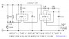
I want to build a circuit that will employ 2 relays, one to close and release the speakerphone button on my telephone, then 1/2 second later the second relay would close then release the redial button. The phone requires the release of the speaker phone button b4 it allows redial. Could the attached circuit work by connecting the speakerphone relay to the output of timer A, then the redial relay to the output of timer B. or any other ideas.


Thanks,
Haxxx.
 

Attachments

  • back-to-back.jpg
    back-to-back.jpg
    50.1 KB · Views: 177
I won't comment on the circuit, but I'll offer a suggestion to replace the relays. Find out the largest resistor that's necessary to make the contact work. As long as it's slightly greater than 200 ohms, you'll be fine with this interface. The largest current you would hve to supply is 40 mA.

These, VTL5C1 **broken link removed** see the data sheet or any other OptoFET work well for interfacing. The nice part about this particular one is the wire leads.
 
No that circuit won't work. It provides a beep tone once the left 555 is triggered.

You can do it with 3 555s, each configured in the monostable timer mode:
1) the first 555 is set up just like the left one in your schematic, mono time constant = 1.5seconds,
2) the second 555 is triggered from the output of the first though a capacitor, mono time constant = .5seconds,
3) the third 555 is triggered from the output of the first through a capacitor & inverter (e.g. a transistor inverter), mono time constant = .5seconds.

The outputs from the 2nd & 3rd 555s will be the pulses that drive the relays.

The way it works is the 1st timer outputs a 1.5second pulse; on the rising edge of this pulse, the 3rd timer is triggered & it outputs a .5second pulse. On the falling edge (i.e. after 1.5 seconds), the 2nd timer is triggered and outputs a .5second pulse.

Hope you can understand my ramblings.
 
Didn't quite follow ur post but u got me to thinking....
Could i alternatively have my first timer (Timer A) only provide power to my entire circuit through a transistor for 3.5 seconds. Timer A powers timer B which feeds an inverter.
Operation:
When the switch of timer A is pressed its output supplies power through the transistor
to Timer B(no switch). timer B output goes high for 1.5s activating speakerphone relay and the inverter input keeping inverter output low. When timer B output goes low, inverter output goes high, activating redial relay for a short time before power is removed from the entire circuit by timer A. Seems a little crude, but might work, did i miss anything? any potential pitfalls?

Regards,
H.
 
OK what you need is two momentary relays one with a delay.
May be something like this;
 

Attachments

  • RC%20Relay%20Delay.gif
    RC%20Relay%20Delay.gif
    4.8 KB · Views: 177
I would use reed relays with the diodes built in and a 555 timer for the delay on the 2nd momentary relay.
Andy
 
When the switch of timer A is pressed its output supplies power through the transistor
to Timer B(no switch). timer B output goes high for 1.5s activating speakerphone relay and the inverter input keeping inverter output low. When timer B output goes low, inverter output goes high, activating redial relay for a short time before power is removed from the entire circuit by timer A. Seems a little crude, but might work, did i miss anything? any potential pitfalls?
It might work, but it doesn't give the relay pulses that you asked for in the OP. There is next to no 'off time' between the speaker button phone release and the redial button press in this case. You can easily check if this will work using your finger on the phone.

Didn't quite follow ur post but u got me to thinking....
If the above doesn't work, here's my original proposal:
 

Attachments

  • back-to-back.png
    back-to-back.png
    4.6 KB · Views: 177
One more quick question, a couple years ago i built a 555 circuit very similar to the one on the left. I was advised to
place a diode across the 100k to prevent the voltage at pin 2 from rising above the supply voltage when the cap discharges,
just like to know if it's necessary over overkill.
 
I can see where they were coming from; when the switch is released, the capacitor could potentially go to twice the rail voltage. Personally: I wouldn't bother, as the current is limited by the resistor that's connected to the switch (value not marked, but should be between 10k-100k), and the BJTs on the input should zener away any excess happily. Professionally (if I'm allowed to use that word): if I were worried, I might run some checks on the induced spike or just simply add the diode. But really, go for your life; diodes don't cost much & adding them certainly won't hurt.

EDIT: so in answer to your question: I'm not 100% certain if it's required for long term reliability, maybe someone else on the forum knows for sure.
 
Last edited:
Status
Not open for further replies.

Latest threads

New Articles From Microcontroller Tips

Back
Top