Hi WTP,
I think you should take another look at this. The result is certainly not y[n]=h[n]. That could only occur if x[n] was the sampling function:
x[0]=1
x[1]=0
x[2]=0
x[3]=0
etc.,
which shows only x[0] as being equal to 1 and all the rest from -inf to +inf are equal to zero. That is the so called "Sampling Function".
With more than one value for the x sequence we'll see an actual convolution where x must be convolved with h and that involves a sum which here results in various sums of a variable number of samples of h (see previous post).
Notice how close his h[n] resemble the impulse function for an RC network. You can liken this example to an RC network being driven by a voltage pulse and taking the result from across the cap. The output is definitely NOT the same as the impulse response. The only way to get that is to drive the network with an impulse, and note that the discrete equivalent is not an x with several values not equal to zero, but only one value not equal to zero.
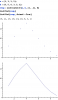
So the resulting sequence will look like (but not exactly equal to) a sampled RC low pass filter driven by a pulse, which results in a waveform that looks sort of like an ocean wave just before it crashes into the shore: it will rise up as a concave downward curve, and fall downward as a concave upward curve if we were to connect the top of all the resulting samples with lines.