stevenh
Member
That title probably makes zero sense.... but here we go at my attempt to describe a common problem I've had with Model Railway electronics.
The DC outputs on many devices vary between either having a common wire and then two 'other' (sometimes ground, sometimes +VCC) wires for providing output current controlled by "something".
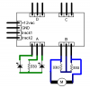
Enter the DCC Accessory Decoder. It has 4 outputs of one common wire (in this case VCC) and 2 ground wires to allow two devices to be operated.
See the diagram attached... it's copied direct from the manual as to how they recommend you wire up LEDs (straightforward) and a switch machine (a standard coil motor.)
They don't recommend you power the switch machine perpetually in the manual and you definately don't in real life... the decoder simply provides a burst on pin 1+2 or 2+3.
This is all well and good... the 330ohm (supplied value) resistors seem to take a blow alternately and allow enough current to pass to fire the motor.
Now, my problem is that the device I am trying to power requires a bit more juice... It's a Japanese double crossover (see attachment two) and all 4 points get powered at one time.
This is done by either applying +12v DC on the wires in either polarity to switch in either direction... i.e. they're either all straight or all switched.
Now, therefore I simply have two wires coming out and it's the exact same circuit as the switch machine in the diagram provided with the decoder. My issue is that the power given during the burst ain't good enough") ... I believe the 330ohm resistors are stealing too much?
... I believe the 330ohm resistors are stealing too much?
I'd love to know if there is a better way to do this? I've just tried to power just a single point with the 330ohms as they've shown and it also doesn't fire... only when I put the two wires directly into 1+2 does the point switch.. of course I then can't switch it back.
Now... I know I can slap some relays in and do some magic with that... but I was wondering if there was just a simpler way to wire this up? I attempted to use 1N4001 diodes to try and allow the current to flow in the right directions but I failed...
Anyway, if anyone can give advice on the whole concept of converting +/-/+ to +/- reversing then I'd be greatly appreciative
Thanks, Steven.
The DC outputs on many devices vary between either having a common wire and then two 'other' (sometimes ground, sometimes +VCC) wires for providing output current controlled by "something".
Enter the DCC Accessory Decoder. It has 4 outputs of one common wire (in this case VCC) and 2 ground wires to allow two devices to be operated.
See the diagram attached... it's copied direct from the manual as to how they recommend you wire up LEDs (straightforward) and a switch machine (a standard coil motor.)
They don't recommend you power the switch machine perpetually in the manual and you definately don't in real life... the decoder simply provides a burst on pin 1+2 or 2+3.
This is all well and good... the 330ohm (supplied value) resistors seem to take a blow alternately and allow enough current to pass to fire the motor.
Now, my problem is that the device I am trying to power requires a bit more juice... It's a Japanese double crossover (see attachment two) and all 4 points get powered at one time.
This is done by either applying +12v DC on the wires in either polarity to switch in either direction... i.e. they're either all straight or all switched.
Now, therefore I simply have two wires coming out and it's the exact same circuit as the switch machine in the diagram provided with the decoder. My issue is that the power given during the burst ain't good enough
... I believe the 330ohm resistors are stealing too much?I'd love to know if there is a better way to do this? I've just tried to power just a single point with the 330ohms as they've shown and it also doesn't fire... only when I put the two wires directly into 1+2 does the point switch.. of course I then can't switch it back.
Now... I know I can slap some relays in and do some magic with that... but I was wondering if there was just a simpler way to wire this up? I attempted to use 1N4001 diodes to try and allow the current to flow in the right directions but I failed...
Anyway, if anyone can give advice on the whole concept of converting +/-/+ to +/- reversing then I'd be greatly appreciative
Thanks, Steven.
Attachments
Last edited:
