Continue to Site

Welcome to our site!

Electro Tech is an online community (with over 170,000 members) who enjoy talking about and building electronic circuits, projects and gadgets. To participate you need to register. Registration is free. Click here to register now.

  • Welcome to our site! Electro Tech is an online community (with over 170,000 members) who enjoy talking about and building electronic circuits, projects and gadgets. To participate you need to register. Registration is free. Click here to register now.

Converter Buck Adjustable Step Down Regulator

Status
Not open for further replies.

meddyliol

New Member
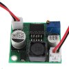
I bought one of these to use with a 12V supply so that I could get a variable output voltage. When I connected the 12V the output from the converter started off at about 6V and gradually increased to about 11.36V. Almost like a capacitor charging over a very very long time constant. I adjusted the output to 9V and then switched off. When I switched back on again I expected it to be 9V but no, it went back to about 6V and climbed back up again (taking about 20 minutes). Of course, there could be a fault with the converter but was wondering if anyone else had had any such problems before I send it back. I enclose an attached file showing the item.

Thanks

Brian
 

Attachments

  • Buck converter.JPG
    Buck converter.JPG
    30.4 KB · Views: 173
The first thing I would ask for would be a schematic of the board, but there probably wasn't one included.

But, the circuit was probably copied right off of the data sheet for the PWM chip. Can you tell us the part number of the big black part in the middle?
 
Thanks to ronsimpson, I put a 2M2 resistor in as a load and it worked as it should. I would really like a cct diagram of it so I could understand what is going on. The only thing I can find on that 'big black part' is the number 330. I would be interested in why it needs a load though.

Thanks for your help

Brian
 
Hi,

Happy to see you got it to work, but you should use a smaller resistor than that. 1k would be better for example.

As to the circuit, check out the LM2596 as i would bet that is the part being used for the converter chip.

In the circuit shown, they may have left out Cff and the two resistors are made up by the pot itself or else they used a pot and one resistor.
 

Attachments

  • LM2596-1.gif
    LM2596-1.gif
    27.7 KB · Views: 169
Last edited:
Status
Not open for further replies.

New Articles From Microcontroller Tips

Back
Top