Continue to Site

Welcome to our site!

Electro Tech is an online community (with over 170,000 members) who enjoy talking about and building electronic circuits, projects and gadgets. To participate you need to register. Registration is free. Click here to register now.

  • Welcome to our site! Electro Tech is an online community (with over 170,000 members) who enjoy talking about and building electronic circuits, projects and gadgets. To participate you need to register. Registration is free. Click here to register now.

Convert Sine Wave To Square Wave for External Clock In

Status
Not open for further replies.

vidi

New Member
Hey all, I'm new to this forum, so let me say hello and I thank everyone in advance for any help I may receive and hope to be able to help others in my own right as time goes on!

So my question is:
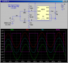
Does anyone have a way to convert a sine wave to a square wave? I've seen several methods available (comparator, schmidt, differential line, etc...) and I'm wondering if anyone has any previous experience and could point me in the right direction.

I'm trying to take in a 2v p-p, ground centered sine wave, operating at 60 Hz, and create a reliable input clock signal that's a square wave of 0-5v, also at 60Hz to act as a timer to set my PWM duty cycle on some thyristor pins. The ability to sync the PWM to the sine wave is of predominant importance here because there may be minor fluctuations in the frequency and I'd like my little clock signal to be able to follow that so that my PWM stays in sync with my input wave.

Again- thanks for any info or feedback!
-Vid
 
What supply voltages do you have available? Split supplies? What parts can you get?

Here is just one of many possible solutions:
 

Attachments

  • DF180.png
    DF180.png
    38.7 KB · Views: 775
Last edited:
I have two 5 volt supplies, which are at fairly low power ratings, but should be sufficient to power any of your basic IC's. which are onboard to my control. I have seen that exact Schmit trigger, but the issue I have with that method is that it is inverted; the AC rise is translated as the DC fall on the output.

Without any other IC to re-invert the input, do you know of a way to have the timer output rise with the rise of the AC signal?
 
The problem I've found with a mains clock, is the noise that devices like thyristors can inject, giving multiple edges or false zero crossings. A zero phase(multiple of 360 deg at the mains frequency) low pass filter would be good (i.e. a low pass filter with some phase compensation). The other thing I've used is a PLL, but that requires a bit more design effort.

MikeMI, nice way to get a kind of window comparator with the 555 timer. I'll remember that.
 
Without any other IC to re-invert the input, do you know of a way to have the timer output rise with the rise of the AC signal?

Well, if you can't stand to have even one little bitty inverter after the output, what's wrong with just using a conventional squaring circuit (rail-to-rail-driven op amp/comparator)? That's trivially easy. Especially at 60 Hz.
 
lol. I know it all seems so easy, but it's been so long since I did anything with micro-electronics. If you don't use it you lose it. Thanks for the suggestions all. I've got a comparator rigged up and it is working quite well.
 
...
MikeMI, nice way to get a kind of window comparator with the 555 timer. I'll remember that.

Change R2 to vary the amount of hysteresis.
 
Status
Not open for further replies.

Latest threads

New Articles From Microcontroller Tips

Back
Top